REAR AIR CONDITIONING UNIT REASSEMBLY
PROCEDURE
-
INSTALL REAR EVAPORATOR SUB-ASSEMBLY
-
Sufficiently apply compressor oil to 2 new O-rings and the fitting surfaces of the rear evaporator sub-assembly.
Compressor Oil ND-OIL 8 or equivalent -
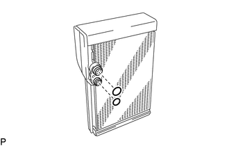
Install the 2 O-rings to the rear evaporator sub-assembly.
Note
Keep the O-rings and O-ring fitting surfaces free from dirt and foreign matter.
-
Install the rear evaporator sub-assembly.
-
-
INSTALL NO. 2 AIR CONDITIONING HARNESS ASSEMBLY
-
Engage the 2 claws.
-
Install the rear cooling unit cover LH with the 12 screws.
-
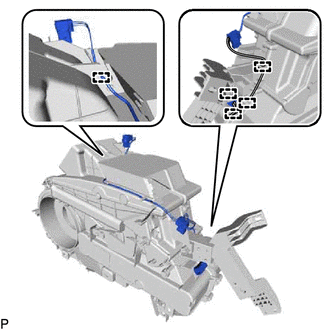
Engage each clamp to install the No. 2 air conditioning harness assembly.
-
-
INSTALL REAR AIR MIX DAMPER SERVO SUB-ASSEMBLY
-
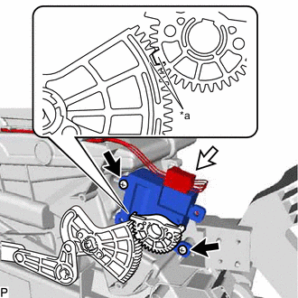
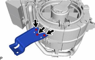
*a Reference Point Using the reference points, install the rear air mix damper servo sub-assembly with the 2 screws.
-
Connect the connector.
-
-
INSTALL REAR MODE DAMPER SERVO SUB-ASSEMBLY
-
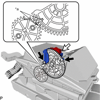
*a Reference Point Using the reference points, install the rear mode damper servo sub-assembly with the 2 screws.
-
Connect the connector.
-
-
INSTALL BLOWER MOTOR CONTROL
-
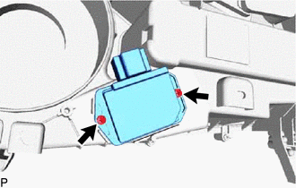
Install the blower motor control with the 2 screws.
-
-
INSTALL REAR BLOWER MOTOR WITH FAN SUB-ASSEMBLY
-
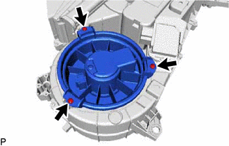
Install the rear blower motor with fan sub-assembly with the 3 screws.
Note
Do not install the rear blower motor with fan sub-assembly if it has been dropped or subjected to a severe impact.
-
-
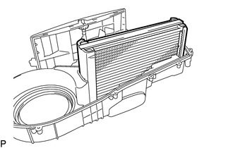
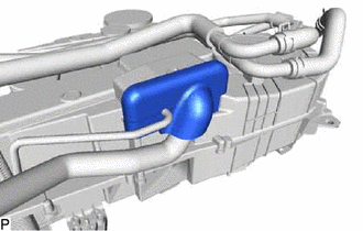
INSTALL HEATER RADIATOR UNIT SUB-ASSEMBLY
-
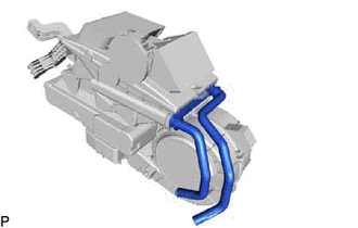
Install the heater radiator unit sub-assembly.
-
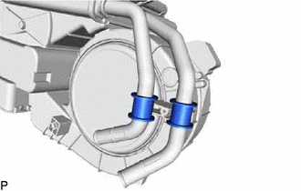
Install the 2 bushes.
-
Install the clamp with the screw.
-
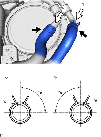
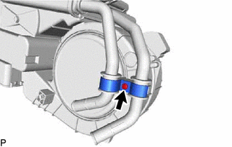
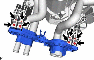
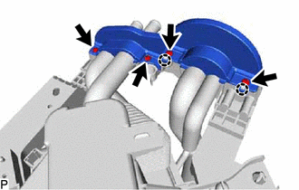
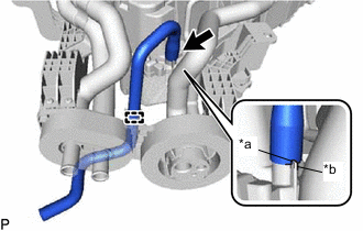
*a View A *b View B *c Marking (Blue) *d Marking (Pink) *e Clip Installation Angle (60 to 120°) Connect the heater water pipe and hose sub-assembly and engage the 2 clips within the area shown in the illustration.
-
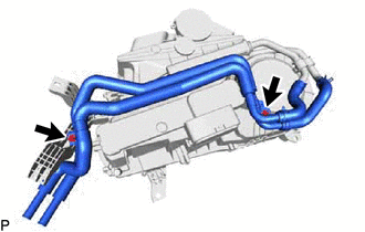
Install the heater water pipe and hose sub-assembly with the 2 screws.
-
Install the bracket with the 3 screws.
-
-
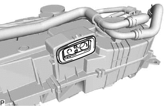
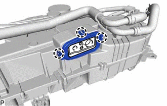
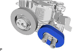
INSTALL REAR COOLING UNIT EXPANSION VALVE
-
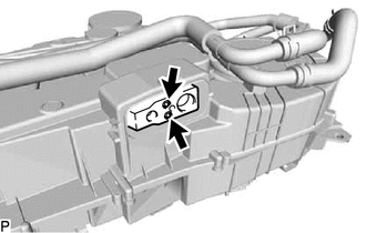
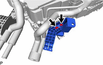
Using a 4 mm hexagon wrench, install the rear cooling unit expansion valve with the 2 hexagon bolts.
- Torque:
- 3.5 N*m { 36 kgf*cm, 31 in.*lbf }
-
Install the grommet.
-
Engage the 3 claws to install the plate.
-
Remove the vinyl tape from the air conditioner tube and accessory assembly.
-
Sufficiently apply compressor oil to 2 new O-rings and the fitting surfaces of the air conditioner tube and accessory assembly.
Compressor Oil ND-OIL 8 or equivalent -
Install the 2 O-rings to the air conditioner tube and accessory assembly.
-
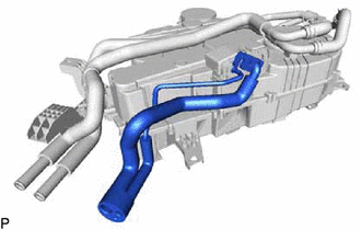
Temporarily install the air conditioner tube and accessory assembly.
-
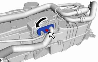
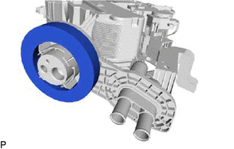
Rotate the hook connector as shown in the illustration.
-
Insert the tube joint into the fitting hole securely and using a 4 mm hexagon wrench, tighten the hexagon bolt.
- Torque:
- 9.8 N*m { 100 kgf*cm, 87 in.*lbf }
-
Install the bracket with the 2 screws.
-
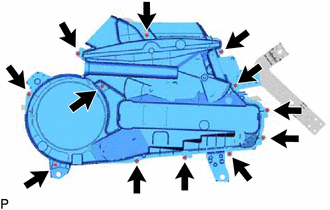
Install the cover with the 8 screws.
-
Engage the 2 claws.
-
Install the cover with the 4 screws.
-
Install a new packing.
-
Install a new packing.
-
-
INSTALL NO. 1 COOLING UNIT PACKING
-
Install a new No. 1 cooling unit packing.
-
-
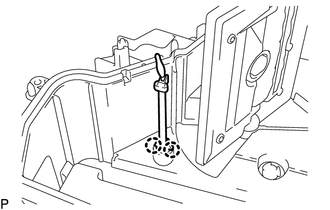
INSTALL DRAIN COOLER HOSE
-
*a Hose Notch *b Rear Cooling Unit Assembly Rib Align the hose notch with the rear cooling unit assembly rib as shown in the illustration and install the drain cooler hose.
-
Engage the clamp.
-