FRONT AIR CONDITIONING UNIT INSTALLATION
PROCEDURE
-
TEMPORARILY INSTALL AIR CONDITIONING UNIT ASSEMBLY
-
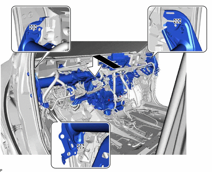
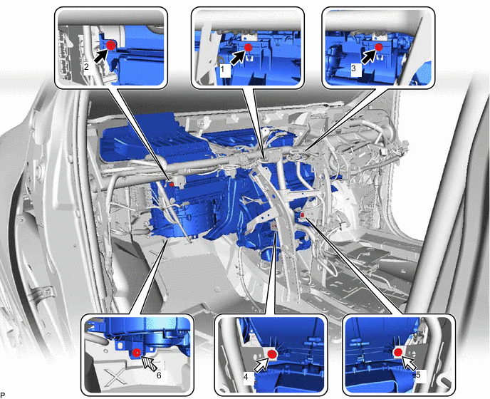
Engage the 2 claws.
-
Temporarily install the air conditioning unit assembly to the instrument panel reinforcement assembly with the 3 bolts.
-
-
INSTALL INSTRUMENT PANEL REINFORCEMENT ASSEMBLY WITH AIR CONDITIONING UNIT
Note
-
Be sure to support the air conditioning unit assembly when installing it. Failure to do so may cause the bracket of the air conditioning unit assembly to break.
-
When installing the air conditioning unit assembly, eliminate static electricity by touching the vehicle body to prevent the components from being damaged.
-
Engage the 3 guides to temporarily install the instrument panel reinforcement assembly with air conditioning unit as shown in the illustration.
-
Install the 6 bolts as shown in the illustration.
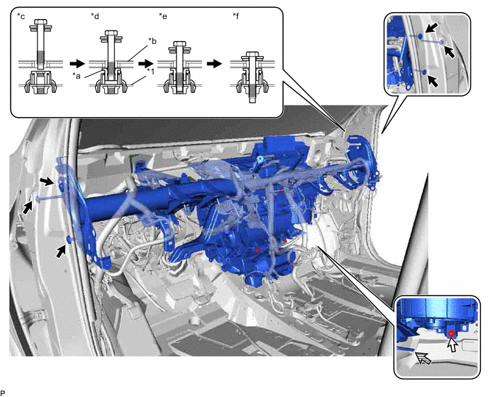
*1 Instrument Panel Reinforcement Assembly - - *a Movable Collar *b Vehicle Body *c Step 1 *d Step 2 *e Step 3 *f Step 4 
Bolt 
Nut - Torque:
- 20 N*m { 204 kgf*cm, 15 ft.*lbf }
-
Temporarily install the nut.
-
Connect the drain cooler hose.
-
Install the 2 hole plugs.
-
Engage the claw to connect the drain cooler hose to the piping clamp.
-
Install the 2 bolts.
- Torque:
- 20 N*m { 204 kgf*cm, 15 ft.*lbf }
-
Install the 2 hole plugs.
-
Engage each clamp.
-
Connect each connector.
-
for LHD:
-
Connect the 4 earth wires with the 4 bolts.
- Torque:
- 8.5 N*m { 87 kgf*cm, 75 in.*lbf }
-
-
for RHD:
-
Connect the 3 earth wires with the 3 bolts.
- Torque:
- 8.5 N*m { 87 kgf*cm, 75 in.*lbf }
-
-
-
INSTALL INSTRUMENT PANEL SAFETY PAD CAP
-
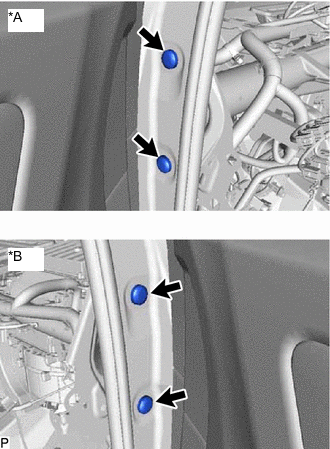
*A for LH Side *B for RH Side Install 4 new instrument panel safety pad caps.
-
-
INSTALL NO. 2 INSTRUMENT PANEL BRACE SUB-ASSEMBLY
-
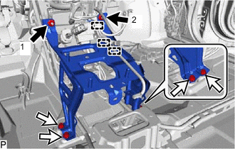
Install the No. 2 instrument panel brace sub-assembly with the bolt, screw and 2 nuts.
- Torque:
- Bolt
- 20 N*m { 204 kgf*cm, 15 ft.*lbf }
Tech Tips
Do not fully tighten the screw.
-
Engage each clamp.
-
-
INSTALL NO. 1 INSTRUMENT PANEL BRACE SUB-ASSEMBLY
-
Install the No. 1 instrument panel brace sub-assembly with the 2 bolts, screw and 2 nuts.
- Torque:
- Bolt
- 20 N*m { 204 kgf*cm, 15 ft.*lbf }
Tech Tips
Do not fully tighten the screw.
-
Connect the earth wire with the bolt.
- Torque:
- 8.5 N*m { 87 kgf*cm, 75 in.*lbf }
-
Engage each clamp.
-
-
FULLY TIGHTEN AIR CONDITIONING UNIT ASSEMBLY
-
for LHD:
-
Tighten the 3 bolts, 2 screws and nut.
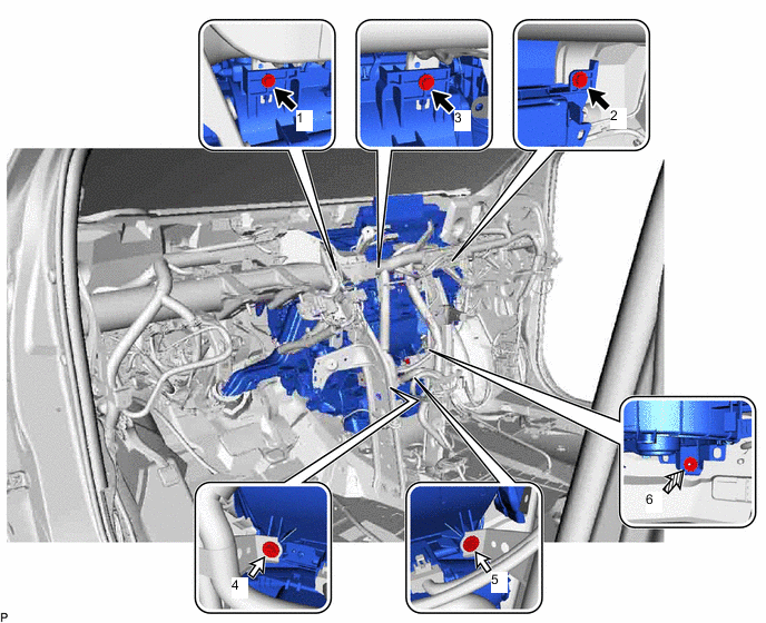
Bolt Screw 
Nut - - - Torque:
- Bolt
- 9.8 N*m { 100 kgf*cm, 87 in.*lbf }
- Nut
- 5.0 N*m { 51 kgf*cm, 44 in.*lbf }
Note
Tighten the bolts, screws and nut in the order shown in the illustration to install the air conditioning unit assembly.
-
-
for RHD:
-
Tighten the 3 bolts, 2 screws and nut.
Bolt Screw Nut - - - Torque:
- Bolt
- 9.8 N*m { 100 kgf*cm, 87 in.*lbf }
- Nut
- 5.0 N*m { 51 kgf*cm, 44 in.*lbf }
Note
Tighten the bolts, screws and nut in the order shown in the illustration to install the air conditioning unit assembly.
-
-
-
INSTALL DRIVING SUPPORT ECU ASSEMBLY (for RHD)
w/ Toyota Safety Sense P
-
INSTALL WINDSHIELD WIPER RELAY ASSEMBLY (w/ Rain Sensor)
-
INSTALL SHIFT LEVER SUPPORT
-
Nut Bolt Install the 2 nuts.
- Torque:
- 12 N*m { 122 kgf*cm, 9 ft.*lbf }
Note
Tighten the nuts in the order shown in the illustration.
-
Install the shift lever support with the 4 bolts.
- Torque:
- 12 N*m { 122 kgf*cm, 9 ft.*lbf }
-
Engage each clamp.
-
Connect each connector.
-
-
INSTALL TRANSMISSION FLOOR SHIFT ASSEMBLY
for U760E Automatic Transmission / Transaxle:
for UA80E Automatic Transmission / Transaxle:
for UA80F Automatic Transmission / Transaxle:
-
INSTALL REAR NO. 3 AIR DUCT
-
Engage the 2 claws to install the rear No. 3 air duct.
-
-
INSTALL REAR NO. 4 AIR DUCT
-
Install the rear No. 4 air duct with the clip.
-
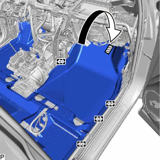

Fastener Install the front floor carpet assembly to the original position as shown in the illustration.
-
Engage the fastener and 4 guides.
-
-
INSTALL REAR NO. 1 AIR DUCT
-
Engage the 2 claws to install the rear No. 1 air duct.
-
Engage the clamp to connect the wire harness.
-
-
INSTALL REAR NO. 2 AIR DUCT
-
Install the rear No. 2 air duct with the clip.
-
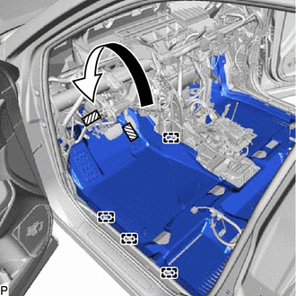
Fastener Install the front floor carpet assembly to the original position as shown in the illustration.
-
Engage the 2 fasteners and 4 guides.
-
-
INSTALL COOLER (ROOM TEMP. SENSOR) THERMISTOR (for Automatic Air Conditioning System)
-
Connect the aspirator and connector to install the cooler (room temp. sensor) thermistor.
-
-
INSTALL WIRE HARNESS CLAMP BRACKET (for LHD)
-
Install the wire harness clamp bracket with the nut.
-
Engage the 3 clamps.
-
-
INSTALL INSTRUMENT PANEL JUNCTION BLOCK ASSEMBLY WITH MAIN BODY ECU
for LHD:
for RHD:
-
INSTALL AIR CONDITIONING AMPLIFIER ASSEMBLY
-
INSTALL ECU INTEGRATION BOX RH (for LHD)
-
INSTALL ECU INTEGRATION BOX LH (for RHD)
-
Install the ECU integration box LH with the bolt and 2 nuts.
-
Engage the 2 clamps.
-
Connect each connector.
-
-
INSTALL STEERING POST ASSEMBLY
-
INSTALL INSTRUMENT PANEL SAFETY PAD SUB-ASSEMBLY
-
INSTALL FRONT SEAT ASSEMBLY LH (for Manual Seat)
-
INSTALL FRONT SEAT ASSEMBLY LH (for Power Seat)
-
INSTALL FRONT SEAT ASSEMBLY RH (for Manual Seat)
Tech Tips
Use the same procedure as for the LH side.
-
INSTALL FRONT SEAT ASSEMBLY RH (for Power Seat)
Tech Tips
Use the same procedure as for the LH side.
-
CONNECT INLET HEATER WATER HOSE
-
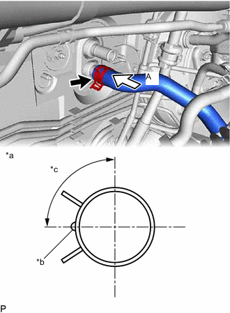
*a View A *b for 1AR-FE w/o ATF Warmer:
Marking (Orange)
for 1AR-FE w/ ATF Warmer:
Marking (Pink)
for 2GR-FKS:
Marking (Blue)
*c Clip Installation Angle (60 to 120°) Connect the inlet heater water hose with the marking facing left and engage the clip within the area shown in the illustration.
Note
Do not apply excessive force to the inlet heater water hose.
-
-
CONNECT OUTLET HEATER WATER HOSE
-
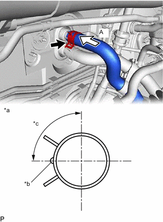
*a View A *b for 1AR-FE w/o ATF Warmer:
Marking (Orange)
for 1AR-FE w/ ATF Warmer:
Marking (Pink)
for 2GR-FKS:
Marking (Blue)
*c Clip Installation Angle (15 to 75°) Connect the outlet heater water hose with the marking facing left and engage the clip within the area shown in the illustration.
Note
Do not apply excessive force to the outlet heater water hose.
-
-
CONNECT AIR CONDITIONER TUBE AND ACCESSORY ASSEMBLY
-
Remove the vinyl tape from the air conditioner tube and accessory assembly.
-
Sufficiently apply compressor oil to a new O-ring and the fitting surface of the air conditioner tube and accessory assembly.
Compressor Oil ND-OIL 8 or equivalent -
Install the O-ring to the air conditioner tube and accessory assembly.
-
Connect the air conditioner tube and accessory assembly.
-
-
CONNECT SUCTION HOSE SUB-ASSEMBLY
-
Remove the vinyl tape from the suction hose sub-assembly.
-
Sufficiently apply compressor oil to a new O-ring and the fitting surface of the suction hose sub-assembly.
Compressor Oil ND-OIL 8 or equivalent -
Install the O-ring to the suction hose sub-assembly.
-
Connect the suction hose sub-assembly.
-
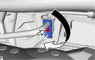
Rotate the hook connector as shown in the illustration.
-
Insert the hose joint into the fitting hole securely and install the bolt.
- Torque:
- 9.8 N*m { 100 kgf*cm, 87 in.*lbf }
-
-
INSTALL OUTER COWL TOP PANEL SUB-ASSEMBLY (for 2GR-FKS)
for LHD:
for RHD:
-
INSTALL WINDSHIELD WIPER MOTOR AND LINK ASSEMBLY (for 2GR-FKS)
-
INSTALL COWL TOP VENTILATOR LOUVER SUB-ASSEMBLY
-
INSTALL FRONT FENDER TO COWL SIDE SEAL LH
-
INSTALL FRONT FENDER TO COWL SIDE SEAL RH
-
INSTALL FRONT WIPER ARM AND BLADE ASSEMBLY LH
-
INSTALL FRONT WIPER ARM AND BLADE ASSEMBLY RH
-
INSTALL FRONT WIPER ARM HEAD CAP
-
CONNECT CABLE TO NEGATIVE BATTERY TERMINAL
Note
When disconnecting the cable, some systems need to be initialized after the cable is reconnected.
-
ADD ENGINE COOLANT (for 1AR-FE)
-
ADD ENGINE COOLANT (for 2GR-FKS)
-
INSPECT FOR COOLANT LEAK (for 1AR-FE)
-
INSPECT FOR COOLANT LEAK (for 2GR-FKS)
-
CHARGE AIR CONDITIONING SYSTEM WITH REFRIGERANT
-
WARM UP ENGINE
-
INSPECT FOR REFRIGERANT LEAK
-
INITIALIZE SERVO MOTOR (for Manual Air Conditioning System)
-
INITIALIZE SERVO MOTOR (for Automatic Air Conditioning System)