FRONT AIR CONDITIONING UNIT REASSEMBLY
PROCEDURE
-
INSTALL NO. 1 AIR CONDITIONING RADIATOR DAMPER SERVO SUB-ASSEMBLY
-
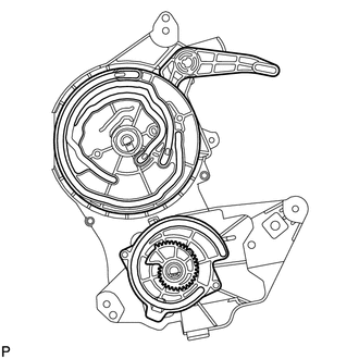
Check that the slots, links and gears of the No. 1 air conditioning radiator damper servo sub-assembly are positioned with the correct orientation as shown in the illustration.
-
Face the contact surfaces of the No. 1 air conditioning radiator damper servo sub-assembly and air conditioning radiator assembly upward.
-
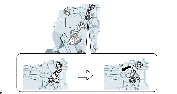
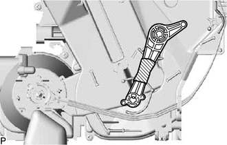
Rotate the link of the air conditioning radiator assembly all the way to the left as shown in the illustration.
-
Rotate the link of the air conditioning radiator assembly to the bottom as shown in the illustration and confirm that the mode switching duct hole is fully closed.
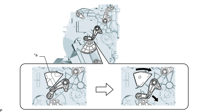
*a Mode Switching Duct Hole - - -
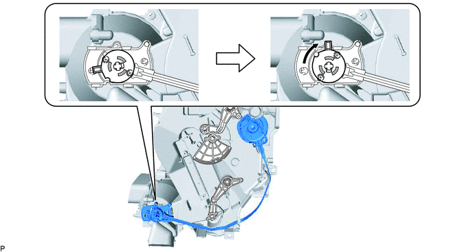
Rotate the lever of the air conditioning radiator assembly to the top as shown in the illustration.
-
Rotate the link of the air conditioning radiator assembly to the in-line position as shown in the illustration.
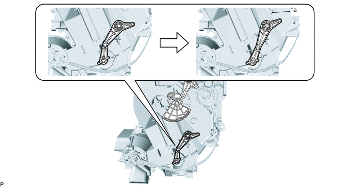
*a In-line Position - - -

Vinyl Tape Wrap the upper and lower links with vinyl tape to hold them in the in-line position.
-
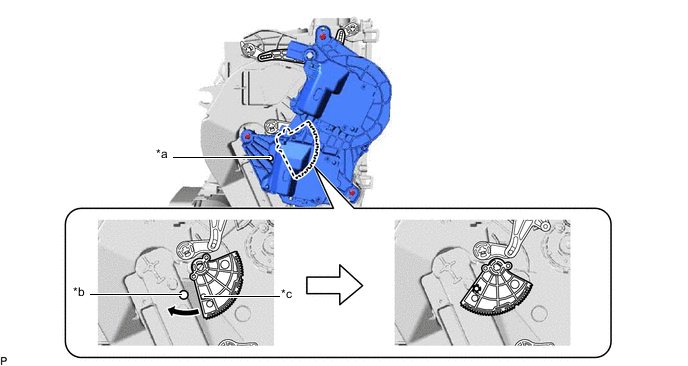
Install the link of the No. 1 air conditioning radiator damper servo sub-assembly to the link guide pin (A) of the air conditioning radiator assembly as shown in the illustration.
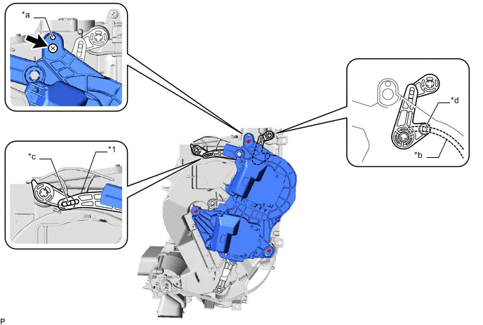
*1 No. 1 Air Conditioning Radiator Damper Servo Sub-assembly - - *a Guide *b No. 1 Air Conditioning Radiator Damper Servo Sub-assembly Slot *c Link Guide Pin (A) *d Link Guide Pin (B) -
Engage the guide of the air conditioning radiator assembly to the No. 1 air conditioning radiator damper servo sub-assembly as shown in the illustration.
-
Temporarily install the screw (up to 4 or 5 threads).
Note
-
Make sure that the link guide pin (B) is inserted in the No. 1 air conditioning radiator damper servo sub-assembly slot.
-
Avoid tilting the air conditioning radiator assembly during installation. This helps to prevent the link guide pins from coming out of position.
-
-
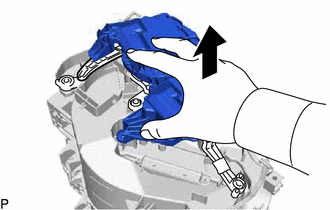
Lift the No. 1 air conditioning radiator damper servo sub-assembly slightly to create clearance.
-
Move the air conditioning radiator assembly gear so that the alignment holes of the No. 1 air conditioning radiator damper servo sub-assembly and air conditioning radiator assembly are aligned.
*a No. 1 Air Conditioning Radiator Damper Servo Sub-assembly Alignment Hole *b Air Conditioning Radiator Assembly Alignment Hole *c Air Conditioning Radiator Assembly Gear Alignment Hole - - -
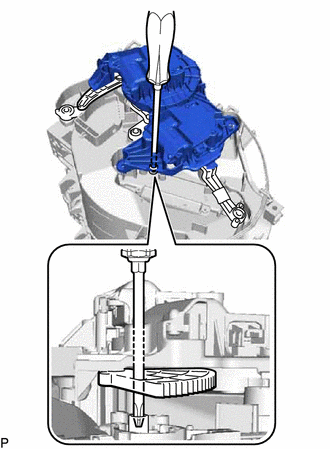
Insert a screwdriver into the alignment holes as shown in the illustration.
-
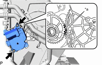
Make sure that all the links and gears are in the positions shown in the illustration.
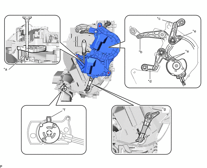
*a Screwdriver is inserted into alignment holes. *b Link guide pin is inserted. *c Link is positioned to left side. *d Link is positioned at bottom. *e Each link guide pin is inserted in its No. 1 air conditioning radiator damper servo sub-assembly slot. *f Lever is positioned at top. *g Links are in-line. - - -
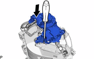
Push the No. 1 air conditioning radiator damper servo sub-assembly into position.
Note
-
Make sure that the No. 1 air conditioning radiator damper servo sub-assembly is fully pushed into position.
-
After pushing the No. 1 air conditioning radiator damper servo sub-assembly into position, keep it in place by holding it until the screws are installed.
Tech Tips
Push the No. 1 air conditioning radiator damper servo sub-assembly until a click sound is heard.
-
-
Remove the screwdriver.
-
Fully tighten the top screw, and then install the No. 1 air conditioning radiator damper servo sub-assembly with the 2 screws.
-
Remove the vinyl tape.
-
-
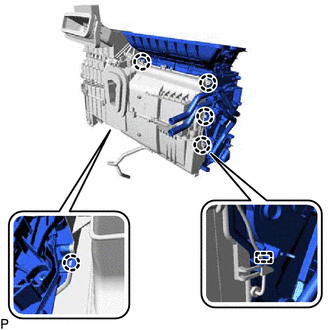
INSTALL HEATER RADIATOR UNIT SUB-ASSEMBLY
-
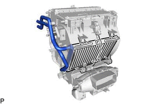
Install the heater radiator unit sub-assembly.
-
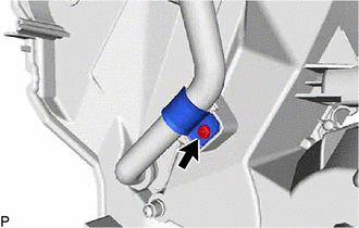
Install the clamp with the screw.
-
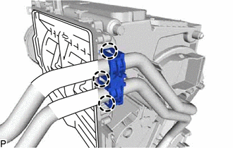
Engage the 3 claws to install the heater clamp.
-
-
INSTALL NO. 2 AIR CONDITIONING RADIATOR DAMPER SERVO SUB-ASSEMBLY (for Automatic Air Conditioning System)
-
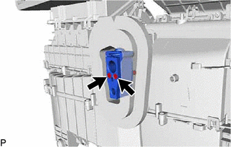
*a Reference Point Using the reference points, install the air mix damper servo sub-assembly with the 2 screws.
-
-
INSTALL QUICK HEATER ASSEMBLY (w/ PTC Heater)
-
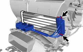
Install the quick heater assembly with the 2 screws.
-
Engage the 2 claws to install the quick heater bracket.
-
Engage the clamp.
-
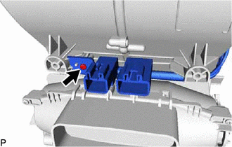
Install the screw.
-
-
INSTALL ASPIRATOR (for Manual Air Conditioning System)
-
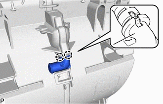
Engage the 2 claws to install the aspirator.
-
-
INSTALL ASPIRATOR (for Automatic Air Conditioning System)
-
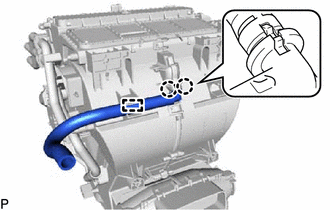
Engage the 2 claws.
-
Engage the clamp to install the aspirator.
-
-
INSTALL NO. 3 AIR DUCT SUB-ASSEMBLY
-
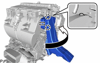
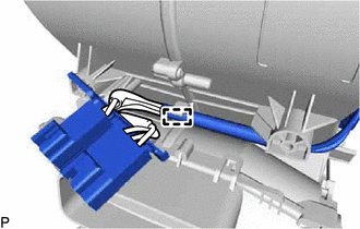
Engage the guide and 2 claws to install the No. 3 air duct sub-assembly as shown in the illustration.
-
-
INSTALL CENTER HEATER TO REGISTER DUCT
-
Engage the 4 claws to install the center heater to register duct.
-
-
INSTALL NO. 1 COOLER THERMISTOR
-
INSTALL NO. 1 COOLER EVAPORATOR SUB-ASSEMBLY
-
Sufficiently apply compressor oil to 2 new O-rings and the fitting surfaces of the No. 1 cooler evaporator sub-assembly.
Compressor Oil ND-OIL 8 or equivalent -
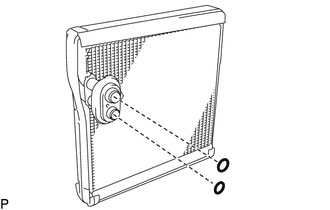
Install the 2 O-rings to the No. 1 cooler evaporator sub-assembly.
Note
Keep the O-rings and O-ring fitting surfaces free from dirt and foreign matter.
-
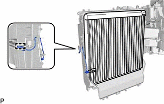
Engage the clamp and install the No. 1 cooler evaporator sub-assembly with No. 1 cooler thermistor.
-
-
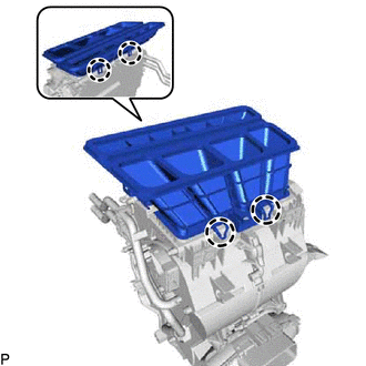
INSTALL AIR CONDITIONING RADIATOR ASSEMBLY
-
Engage the 5 claws.
-
Engage the guide and connect the wire harness.
-
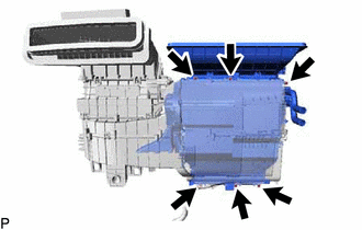
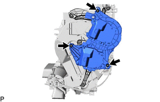
Install the air conditioning radiator assembly to the blower assembly with cooler evaporator sub-assembly with the 6 screws.
-
-
INSTALL COOLER EXPANSION VALVE
-
Using a 4 mm hexagon wrench, install the cooler expansion valve with the 2 hexagon bolts.
- Torque:
- 3.5 N*m { 36 kgf*cm, 31 in.*lbf }
-
-
INSTALL AIR CONDITIONING HARNESS ASSEMBLY
-
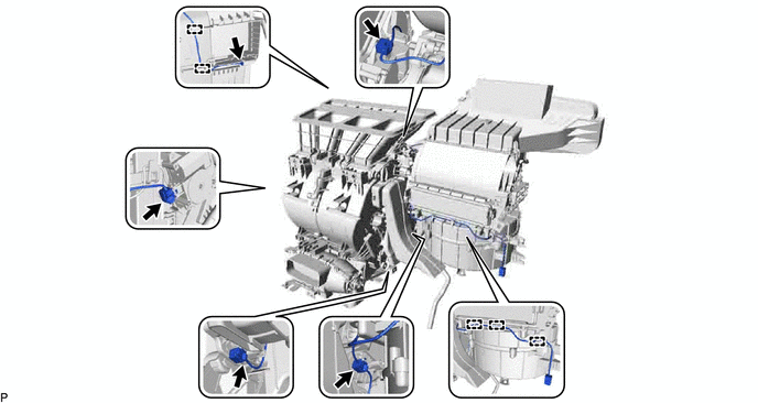
for LHD:
-
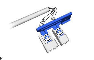
Engage each clamp to install air conditioning harness assembly.
-
Connect each connector.
-
-
for RHD:
-
Engage each clamp to install the air conditioning harness assembly.
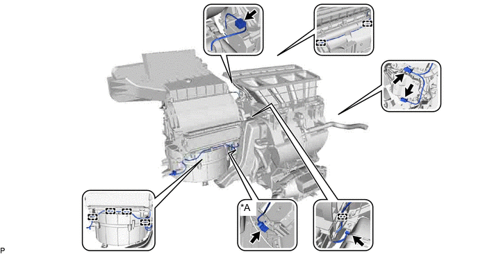
*A for Automatic Air Conditioning System - - -
Connect each connector.
-
-