POWER DOOR LOCK CONTROL SYSTEM Power Source Circuit
DESCRIPTION
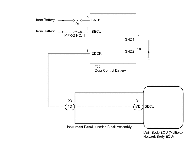
The main power source for the main body ECU (multiplex network body ECU) is supplied via the door control battery.
WIRING DIAGRAM
CAUTION / NOTICE / HINT
Note
-
If the main body ECU (multiplex network body ECU) is replaced, refer to Service Bulletin.*
-
*: w/ Smart Entry and Start System
-
Inspect the fuses for circuits related to this system before performing the following procedure.
-
After performing the following inspection, perform Initialization.
PROCEDURE
-
CHECK HARNESS AND CONNECTOR (DOOR CONTROL BATTERY - BATTERY AND BODY GROUND)
-
Disconnect the F88 door control battery connector.
-
Measure the voltage according to the value(s) in the table below.
Standard Voltage Tester Connection Condition Specified Condition F88-5 (BATB) - Body ground Always 11 to 14 V F88-4 (BECU) - Body ground Always 11 to 14 V -
Measure the resistance according to the value(s) in the table below.
Standard Resistance Tester Connection Condition Specified Condition F88-2 (GND1) - Body ground Always Below 1 Ω F88-10 (GND2) - Body ground Always Below 1 Ω Result Proceed to OK NG
NG 
REPAIR OR REPLACE HARNESS OR CONNECTOR
OK 
-
-
CHECK HARNESS AND CONNECTOR (DOOR CONTROL BATTERY - INSTRUMENT PANEL JUNCTION BLOCK ASSEMBLY)
-
Disconnect the 4D instrument panel junction block assembly connector.
-
Measure the resistance according to the value(s) in the table below.
Standard Resistance Tester Connection Condition Specified Condition F88-3 (EDOR) - 4D-23 Always Below 1 Ω F88-3 (EDOR) or 4D-23 - Body ground Always 10 kΩ or higher Result Proceed to OK NG
NG
REPAIR OR REPLACE HARNESS OR CONNECTOR
OK
-
-
INSPECT DOOR CONTROL BATTERY (POWER OUTPUT)
-
Reconnect the F88 door control battery connector.
-
Turn the ignition switch off.
-
Remove the MPX-B NO. 1 fuse and leave the vehicle as is for 50 minutes.
-
Measure the voltage according to the value(s) in the table below.
Standard Voltage Tester Connection Condition Specified Condition F88-3 (EDOR) - Body ground Ignition switch OFF Below 2 V Result Proceed to OK NG
NG
REPLACE DOOR CONTROL BATTERY Click here
OK
-
-
INSPECT DOOR CONTROL BATTERY (INTERNAL CIRCUIT)
-
Reconnect the F88 door control battery connector.
-
Install the MPX-B NO. 1 fuse.
-
Measure the voltage according to the value(s) in the table below.
Standard Voltage Tester Connection Condition Specified Condition F88-3 (EDOR) - Body ground Always 11 to 14 V Result Proceed to OK NG
NG
REPLACE DOOR CONTROL BATTERY Click here
OK
-
-
INSPECT INSTRUMENT PANEL JUNCTION BLOCK ASSEMBLY
-
Remove the instrument panel junction block assembly.
-
Remove the main body ECU (multiplex network body ECU).
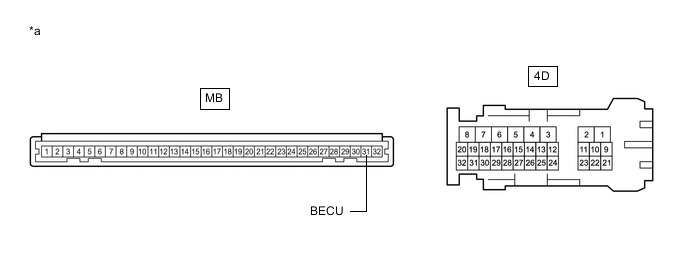
*a Component without harness connected
(Instrument Panel Junction Block Assembly)
- - -
Measure the resistance according to the value(s) in the table below.
Standard Resistance Tester Connection Condition Specified Condition MB-31 (BECU) - 4D-23 Always Below 1 Ω Result Proceed to OK NG
OK
REPLACE MAIN BODY ECU (MULTIPLEX NETWORK BODY ECU) Click here
NG
REPLACE INSTRUMENT PANEL JUNCTION BLOCK ASSEMBLY Click here
-