CAN COMMUNICATION SYSTEM Check Bus 5 Lines for Short Circuit
DESCRIPTION
There may be a short circuit between the CAN main bus lines and/or CAN branch lines when the resistance between terminals 15 (CA5H) and 16 (CA5L) of the central gateway ECU (network gateway ECU) is below 54 Ω.
| Symptom | Trouble Area |
|---|---|
| Resistance between terminals 15 (CA5H) and 16 (CA5L) of the central gateway ECU (network gateway ECU) is below 54 Ω. |
|
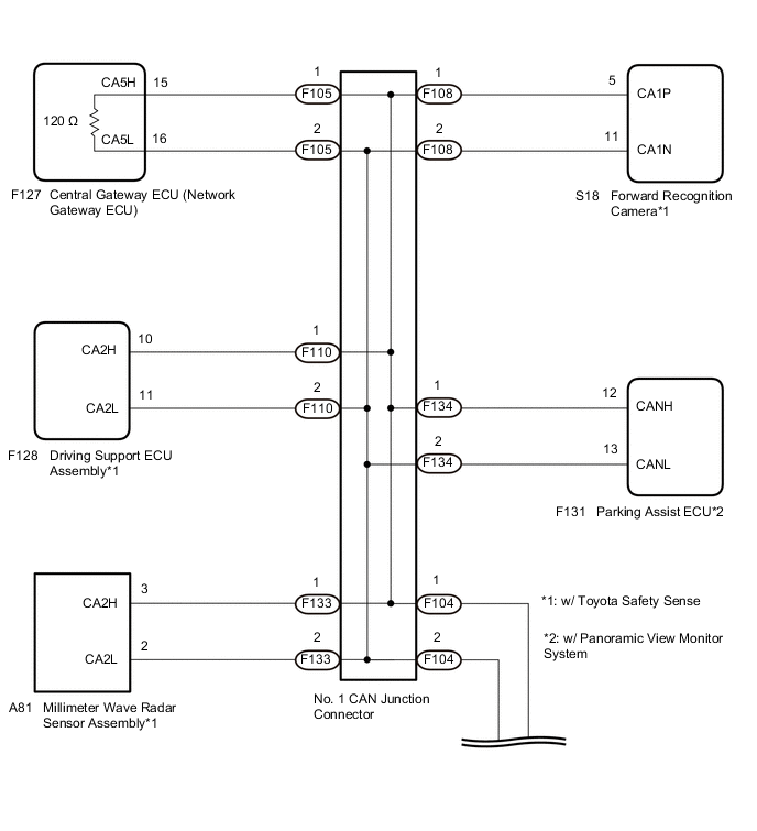
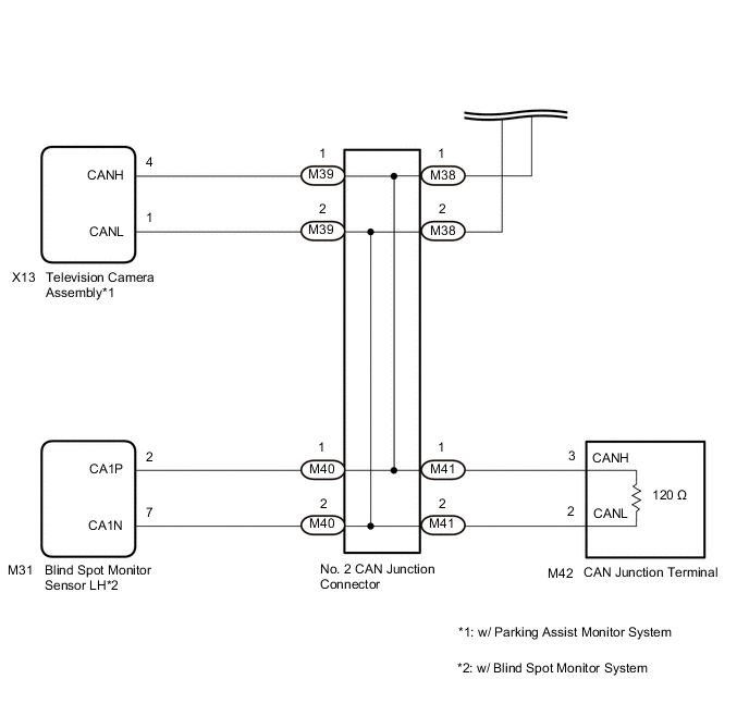
WIRING DIAGRAM
CAUTION / NOTICE / HINT
Note
-
Because the order of diagnosis is important to allow correct diagnosis, make sure to begin troubleshooting using How to Proceed with Troubleshooting when CAN communication system related DTCs are output.
-
Before measuring the resistance of the CAN bus, turn the ignition switch off and leave the vehicle for 1 minute or more without operating the key or any switches, or opening or closing the doors. After that, disconnect the cable from the negative (-) battery terminal and leave the vehicle for 1 minute or more before measuring the resistance.
-
After turning the ignition switch off, waiting time may be required before disconnecting the cable from the negative (-) battery terminal. Therefore, make sure to read the disconnecting the cable from the negative (-) battery terminal notices before proceeding with work.
-
After performing repairs, perform the DTC check procedure and confirm that the DTCs are not output again.
DTC check procedure: Turn the ignition switch to ON and wait at least 20 seconds. Turn the cruise control main switch on and then drive the vehicle at a speed of 36 km/h (22 mph) or more for 9 seconds or more.
-
After the repair, perform the CAN bus check and check that all the ECUs and sensors connected to the CAN communication system are displayed.
Tech Tips
-
Before disconnecting related connectors for inspection, push in on each connector body to check that the connector is not loose or disconnected.
-
When a connector is disconnected, check that the terminals and connector body are not cracked, deformed or corroded.
PROCEDURE
-
CHECK FOR SHORT IN CAN BUS LINES (NO. 1 CAN JUNCTION CONNECTOR - CENTRAL GATEWAY ECU (NETWORK GATEWAY ECU))
-
Disconnect the cable from the negative (-) battery terminal.
-
Disconnect the F105 wire harness connector.
-
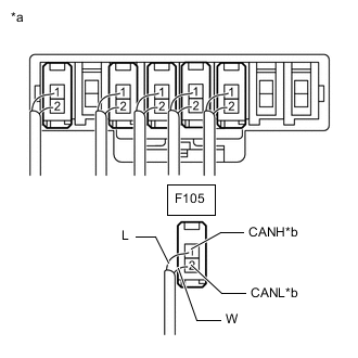
*a Rear view of wire harness connector
(to No. 1 CAN Junction Connector)
*b to Central Gateway ECU (Network Gateway ECU) Measure the resistance according to the value(s) in the table below.
Standard Resistance Tester Connection Condition Specified Condition F105-1 (CANH) - F105-2 (CANL) Cable disconnected from negative (-) battery terminal 108 to 132 Ω Note
-
Before disconnecting the connectors, make a note of where they are connected.
-
Reconnect each connector to its original position.
Result Result OK NG -
NG 
CHECK FOR SHORT IN CAN BUS LINES (CENTRAL GATEWAY ECU (NETWORK GATEWAY ECU)) Click here
OK 
-
-
CHECK FOR SHORT IN CAN BUS LINES (BRANCH LINE)
-
Reconnect the F105 wire harness connector.
-
*a Component with harness connected
(No. 1 CAN Junction Connector)
*b to Central Gateway ECU (Network Gateway ECU) Connect the probes of an electrical tester to terminals 1 (CANH) and 2 (CANL) of the central gateway ECU (network gateway ECU) main line harness connector.
-
While observing the resistance value shown on the electrical tester, disconnect the F108, F110, F133, F134, M39 and M40 connectors from the No. 1 CAN junction connector or No. 2 CAN junction connector one by one until the resistance becomes normal (between 54 and 69 Ω).
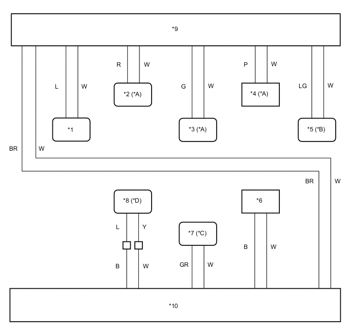
*A w/ Toyota Safety Sense *B w/ Panoramic View Monitor System *C w/ Blind Spot Monitor System *D w/ Parking Assist Monitor System *1 Central Gateway ECU (Network Gateway ECU) *2 Forward Recognition Camera *3 Driving Support ECU Assembly *4 Millimeter Wave Radar Sensor Assembly *5 Parking Assist ECU *6 CAN Junction Terminal *7 Blind Spot Monitor Sensor LH *8 Television Camera Assembly *9 No. 1 CAN Junction Connector *10 No. 2 CAN Junction Connector 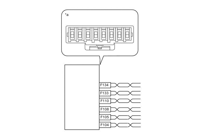
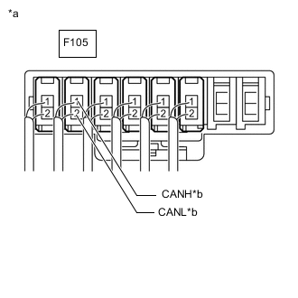
*a Component without harness connected
(No. 1 CAN Junction Connector)
- - Wiring Color No. 1 CAN Junction Connector Side Code Color (CANH Side) Color (CANL Side) No. 2 CAN junction connector F104 BR W Central gateway ECU (network gateway ECU) F105 L W Forward recognition camera*1 F108 R W Driving support ECU assembly*1 F110 G W Millimeter wave radar sensor assembly*1 F133 P W Parking assist ECU*2 F134 LG W
-
*1: w/ Toyota Safety Sense
-
*2: w/ Panoramic View Monitor System
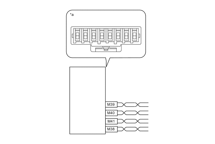
*a Component without harness connected
(No. 2 CAN Junction Connector)
- - Wiring Color No. 2 CAN Junction Connector Side Code Color (CANH Side) Color (CANL Side) No. 1 CAN junction connector M38 BR W Television camera assembly*1 M39 B W Blind spot monitor sensor LH*2 M40 GR W CAN junction terminal M41 B W
-
*1: w/ Parking Assist Monitor System
-
*2: w/ Blind Spot Monitor System
Note
Do not reconnect the disconnected connectors until this inspection is complete because there may be a short in 2 or more branch lines.
Result Result Proceed to The resistance is still below 54 Ω when all the specified connectors are disconnected. (There are no shorts between a pair of branch lines.) A The resistance becomes normal (between 54 and 69 Ω) when a connector is disconnected. (There is a short between one or more pairs of branch lines.) B -
-
When there is a short in one or more of the branch lines:
-
Reconnect all of the connectors to the CAN junction connectors, except for the one that was disconnected last (the short-circuited bus line). Check that the resistance shown on the electrical tester is normal (between 54 and 69 Ω) to confirm that there is a short in the one branch line only.
Tech Tips
-
Connectors that connect to the CAN junction connector can be distinguished by the color of their CAN bus lines.
-
Reconnecting the connectors to non-original positions on the CAN junction connector does not affect system performance. However, it is preferred to reconnect the connectors to their original positions to avoid negative effects on the wiring such as tension on the wire harnesses, and to make future maintenance easier.
-
-
B
CHECK FOR SHORT IN CAN BUS LINES (ECU OR SENSOR) Click here
A
-
-
CHECK FOR SHORT IN CAN BUS LINES (NO. 2 CAN JUNCTION CONNECTOR - CAN JUNCTION TERMINAL)
-
Disconnect the M41 wire harness connector.
-
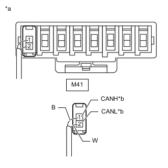
*a Rear view of wire harness connector
(to No. 2 CAN Junction Connector)
*b to CAN Junction Terminal Measure the resistance according to the value(s) in the table below.
Standard Resistance Tester Connection Condition Specified Condition M41-1 (CANH) - M41-2 (CANL) Cable disconnected from negative (-) battery terminal 108 to 132 Ω Note
-
Before disconnecting the connectors, make a note of where they are connected.
-
Reconnect each connector to its original position.
Result Result OK NG -
NG
CHECK FOR SHORT IN CAN BUS LINES (CAN JUNCTION TERMINAL) Click here
OK
-
-
CHECK FOR SHORT IN CAN BUS LINES (NO. 1 CAN JUNCTION CONNECTOR)
-
Disconnect the F104 wire harness connector.
-
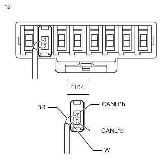
*a Rear view of wire harness connector
(to No. 1 CAN Junction Connector)
*b to No. 2 CAN Junction Connector Measure the resistance according to the value(s) in the table below.
Standard Resistance Tester Connection Condition Specified Condition F104-1 (CANH) - F104-2 (CANL) Cable disconnected from negative (-) battery terminal 1 MΩ or higher Note
-
Before disconnecting the connectors, make a note of where they are connected.
-
Reconnect each connector to its original position.
Result Result OK NG -
OK 
REPLACE NO. 1 CAN JUNCTION CONNECTOR
NG
-
-
CHECK FOR SHORT IN CAN BUS LINES (NO. 2 CAN JUNCTION CONNECTOR - NO. 1 CAN JUNCTION CONNECTOR)
-
Disconnect the M38 wire harness connector.
-
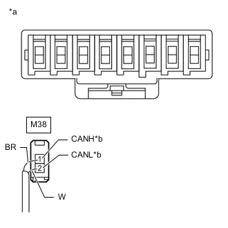
*a Rear view of wire harness connector
(to No. 2 CAN Junction Connector)
*b to No. 1 CAN Junction Connector Measure the resistance according to the value(s) in the table below.
Standard Resistance Tester Connection Condition Specified Condition M38-1 (CANH) - M38-2 (CANL) Cable disconnected from negative (-) battery terminal 1 MΩ or higher Note
-
Before disconnecting the connectors, make a note of where they are connected.
-
Reconnect each connector to its original position.
Result Result OK NG -
OK
REPLACE NO. 2 CAN JUNCTION CONNECTOR
NG
REPAIR OR REPLACE CAN MAIN BUS LINES OR CONNECTOR (NO. 2 CAN JUNCTION CONNECTOR - NO. 1 CAN JUNCTION CONNECTOR)
-
-
CHECK FOR SHORT IN CAN BUS LINES (CAN JUNCTION TERMINAL)
-
Reconnect the M41 wire harness connector.
-
Disconnect the M42 CAN junction terminal connector.
-
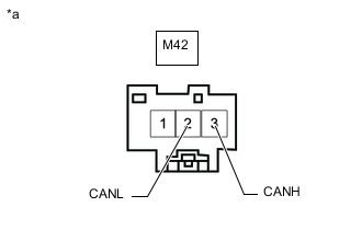
*a Front view of wire harness connector
(to CAN Junction Terminal)
Measure the resistance according to the value(s) in the table below.
Standard Resistance Tester Connection Condition Specified Condition M42-3 (CANH) - M42-2 (CANL) Cable disconnected from negative (-) battery terminal 108 to 132 Ω Result Result OK NG
OK
REPLACE CAN JUNCTION TERMINAL
NG
REPAIR OR REPLACE CAN MAIN BUS LINES OR CONNECTOR (CAN JUNCTION TERMINAL - NO. 2 CAN JUNCTION CONNECTOR)
-
-
CHECK FOR SHORT IN CAN BUS LINES (ECU OR SENSOR)
-
Reconnect all wire harness connectors (No. 1 CAN junction connector and No. 2 CAN junction connector).
-
Disconnect the connector that includes terminals CANH and CANL from the ECU or sensor to which the short circuited branch line is connected.
-
*a Component with harness connected
(Central Gateway ECU (Network Gateway ECU))
Measure the resistance according to the value(s) in the table below.
Standard Resistance Tester Connection Condition Specified Condition F127-15 (CA5H) - F127-16 (CA5L) Cable disconnected from negative (-) battery terminal 54 to 69 Ω Tech Tips
-
If the resistance becomes normal (between 54 and 69 Ω) when the connector is disconnected from the ECU or sensor, there may be a short in the ECU or sensor.
-
If the resistance does not become normal when the connector is disconnected from the ECU or sensor, check for a short in the wire harness and repair or replace the wire harness or connector if necessary.
Result Result OK NG -
OK
REPLACE CORRESPONDING ECU OR SENSOR
NG
REPAIR OR REPLACE CORRESPONDING ECU OR SENSOR BRANCH LINES OR CONNECTOR
-
-
CHECK FOR SHORT IN CAN BUS LINES (CENTRAL GATEWAY ECU (NETWORK GATEWAY ECU))
-
Reconnect the F105 wire harness connector.
-
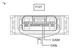
Disconnect the F127 central gateway ECU (network gateway ECU) connector.
-
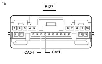
*a Front view of wire harness connector
(to Central Gateway ECU (Network Gateway ECU))
Measure the resistance according to the value(s) in the table below.
Standard Resistance Tester Connection Condition Specified Condition F127-15 (CA5H) - F127-16 (CA5L) Cable disconnected from negative (-) battery terminal 108 to 132 Ω Result Result OK NG
OK
REPLACE CENTRAL GATEWAY ECU (NETWORK GATEWAY ECU) Click here
NG
REPAIR OR REPLACE CAN MAIN BUS LINES OR CONNECTOR (CENTRAL GATEWAY ECU (NETWORK GATEWAY ECU) - NO. 1 CAN JUNCTION CONNECTOR)
-