CAN COMMUNICATION SYSTEM Clearance Warning ECU Communication Stop Mode
DESCRIPTION
| Detection Item | Symptom | Trouble Area |
|---|---|---|
| Clearance Warning ECU Communication Stop Mode | Either condition is met:
|
|
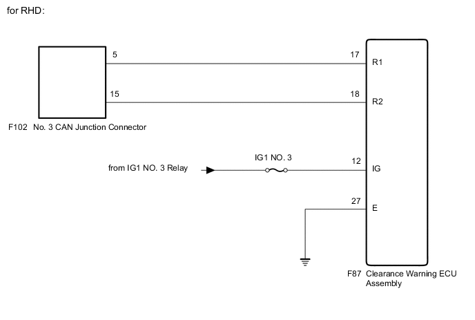
WIRING DIAGRAM
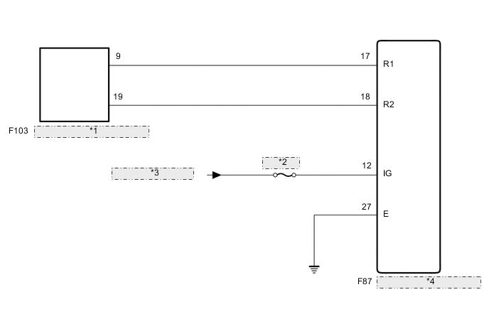
| *1 | No. 4 CAN Junction Connector |
| *2 | IG1 NO. 3 |
| *3 | from IG1 NO. 3 Relay |
| *4 | Clearance Warning ECU Assembly |
CAUTION / NOTICE / HINT
Note
-
Because the order of diagnosis is important to allow correct diagnosis, make sure to begin troubleshooting using How to Proceed with Troubleshooting when CAN communication system related DTCs are output.
-
Before measuring the resistance of the CAN bus, turn the ignition switch off and leave the vehicle for 1 minute or more without operating the key or any switches, or opening or closing the doors. After that, disconnect the cable from the negative (-) battery terminal and leave the vehicle for 1 minute or more before measuring the resistance.
-
After turning the ignition switch off, waiting time may be required before disconnecting the cable from the negative (-) battery terminal. Therefore, make sure to read the disconnecting the cable from the negative (-) battery terminal notices before proceeding with work.
-
After performing repairs, perform the DTC check procedure and confirm that the DTCs are not output again.
DTC check procedure: Turn the ignition switch to ON and wait at least 14 seconds.
-
After the repair, perform the CAN bus check and check that all the ECUs and sensors connected to the CAN communication system are displayed.
-
Inspect the fuses for circuits related to this system before performing the following procedure.
Tech Tips
-
Before disconnecting related connectors for inspection, push in on each connector body to check that the connector is not loose or disconnected.
-
When a connector is disconnected, check that the terminals and connector body are not cracked, deformed or corroded.
PROCEDURE
-
CHECK FOR OPEN IN CAN BUS LINES (CLEARANCE WARNING ECU ASSEMBLY BRANCH LINE)
-
Disconnect the cable from the negative (-) battery terminal.
-
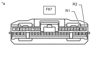
*a Front view of wire harness connector
(to Clearance Warning ECU Assembly)
Disconnect the F87 clearance warning ECU assembly connector.
-
Measure the resistance according to the value(s) in the table below.
Standard Resistance Tester Connection Condition Specified Condition F87-17 (R1) - F87-18 (R2) Cable disconnected from negative (-) battery terminal 54 to 69 Ω Result Result OK NG
NG 
REPAIR OR REPLACE CAN BRANCH LINE OR CONNECTOR (CLEARANCE WARNING ECU ASSEMBLY)
OK 
-
-
CHECK HARNESS AND CONNECTOR (POWER SOURCE CIRCUIT)
-
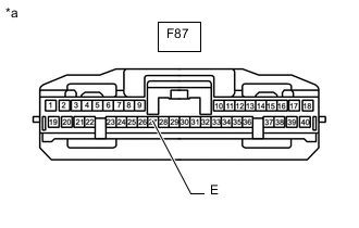
*a Front view of wire harness connector
(to Clearance Warning ECU Assembly)
Measure the resistance according to the value(s) in the table below.
Standard Resistance Tester Connection Condition Specified Condition F87-27 (E) - Body ground Cable disconnected from negative (-) battery terminal Below 1 Ω -
Reconnect the cable to the negative (-) battery terminal.
-
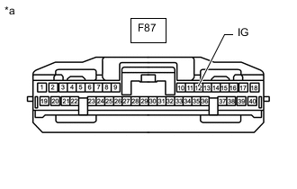
*a Front view of wire harness connector
(to Clearance Warning ECU Assembly)
Measure the voltage according to the value(s) in the table below.
Standard Voltage Tester Connection Condition Specified Condition F87-12 (IG) - Body ground Ignition switch ON 11 to 14 V Result Result OK NG
OK
REPLACE CLEARANCE WARNING ECU ASSEMBLY Click here
NG
REPAIR OR REPLACE HARNESS OR CONNECTOR (POWER SOURCE CIRCUIT)
-