CAN COMMUNICATION SYSTEM TERMINALS OF ECU
Note
-
After turning the ignition switch off, waiting time may be required before disconnecting the cable from the negative (-) battery terminal. Therefore, make sure to read the disconnecting the cable from the negative (-) battery terminal notices before proceeding with work.
-
Turn the ignition switch off before measuring the resistances between CAN main bus lines and between CAN branch lines.
-
Turn the ignition switch off before inspecting CAN bus lines for a ground short.
-
Before measuring the resistance of the CAN bus, turn the ignition switch off and leave the vehicle for 1 minute or more without operating the key, switches or opening or closing the doors. After that, disconnect the cable from the negative (-) battery terminal and leave the vehicle for 1 minute or more before measuring the resistance.
-
This section describes the standard values for all CAN related components.
Tech Tips
-
Operating the ignition switch, any other switches or a door triggers related ECU and sensor communication on the CAN. This communication will cause the resistance value to change.
-
Even after DTCs are cleared, if a DTC is stored again after driving the vehicle for a while, the malfunction may be occurring due to vibration of the vehicle. In such a case, wiggling the ECUs or wire harness while performing the inspection below may help determine the cause of the malfunction.
-
NO. 1 CAN JUNCTION CONNECTOR (for LHD)
-
Check the No. 1 CAN junction connector.
Tech Tips
Connectors that connect to the CAN junction connector can be distinguished by the color of their CAN bus lines. When the connectors have been disconnected from the CAN junction connector, reconnecting the connectors to non-original positions on the CAN junction connector does not affect system performance. However, it is preferred to reconnect the connectors to their original positions to avoid negative effects on the wiring such as tension on the wiring harnesses, and to make future maintenance easier.
-
Connection diagram
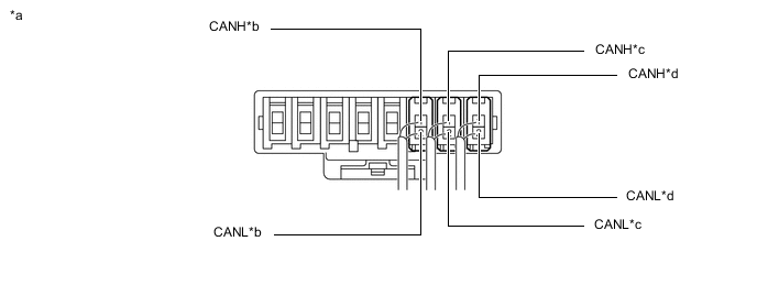
*a Front view of wire harness connector
(No. 1 CAN Junction Connector)
*b to Lane Departure Warning Camera
(w/ Lane Departure Alert System)
(for Sub Bus 2)
*c to Network Gateway ECU
(w/ Blind Spot Monitor System or Parking Assist Monitor System)
(for Sub Bus 2)
*d to No. 2 CAN Junction Connector
(for Sub Bus 2)
-
Check the connection diagram of the components which are connected to the No. 1 CAN junction connector.
Terminal No. (Symbol) Wiring Color Connected to F104-1 (CANH) BR No. 2 CAN junction connector
(for Sub bus 2)
F104-2 (CANL) W F105-1 (CANH) L Network gateway ECU*1
(for Sub bus 2)
F105-2 (CANL) W F108-1 (CANH) R Lane departure warning camera*2
(for Sub bus 2)
F108-2 (CANL) W
-
*1: w/ Blind Spot Monitor System or Parking Assist Monitor System
-
*2: w/ Lane Departure Alert System
-
-
-
-
NO. 2 CAN JUNCTION CONNECTOR (for LHD)
-
Check the No. 2 CAN junction connector.
Tech Tips
Connectors that connect to the CAN junction connector can be distinguished by the color of their CAN bus lines. When the connectors have been disconnected from the CAN junction connector, reconnecting the connectors to non-original positions on the CAN junction connector does not affect system performance. However, it is preferred to reconnect the connectors to their original positions to avoid negative effects on the wiring such as tension on the wiring harnesses, and to make future maintenance easier.
-
Connection diagram
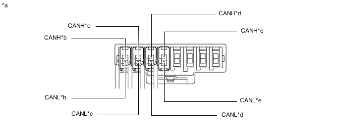
*a Front view of wire harness connector
(No. 2 CAN Junction Connector)
*b to CAN Junction Terminal
(for Sub Bus 2)
*c to Blind Spot Monitor Sensor LH
(w/ Blind Spot Monitor System)
(for Sub Bus 2)
*d to Television Camera Assembly
(w/ Parking Assist Monitor System)
(for Sub Bus 2)
*e to No. 1 CAN Junction Connector
(for Sub Bus 2)
- - -
Check the connection diagram of the components which are connected to the No. 2 CAN junction connector.
Terminal No. (Symbol) Wiring Color Connected to M38-1 (CANH) BR No. 1 CAN junction connector
(for Sub bus 2)
M38-2 (CANL) W M39-1 (CANH) B Television camera assembly*1
(for Sub bus 2)
M39-2 (CANL) W M40-1 (CANH) GR Blind spot monitor sensor LH*2
(for Sub bus 2)
M40-2 (CANL) W M41-1 (CANH) B CAN junction terminal
(for Sub bus 2)
M41-2 (CANL) W
-
*1: w/ Parking Assist Monitor System
-
*2: w/ Blind Spot Monitor System
-
-
-
-
NO. 3 CAN JUNCTION CONNECTOR (for LHD)
-
Check the No. 3 CAN junction connector.
-
Connection diagram
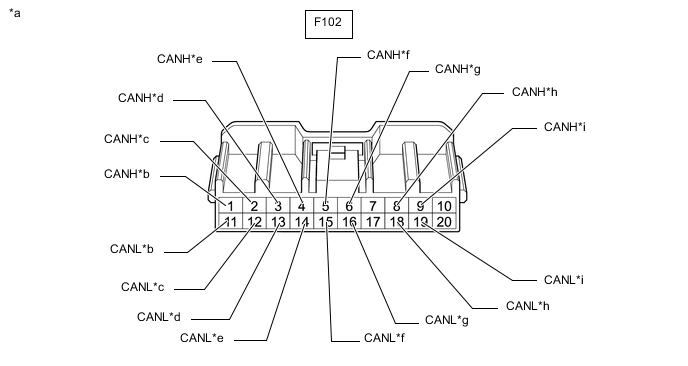
*a Front view of wire harness connector
(No. 3 CAN Junction Connector)
*b to No. 4 CAN Junction Connector
(for V Bus)
*c to ECM
(for V Bus)
*d to DLC3
(for V Bus)
*e to Steering Sensor
(for V Bus)
*f to Power Steering ECU Assembly
(for V Bus)
*g to Main Body ECU (Multiplex Network Body ECU)
(for V Bus)
*h to 4WD ECU Assembly
(for AWD)
(for V Bus)
*i to Headlight Leveling ECU Assembly
(w/ Automatic Headlight Beam Level Control System)
(for V Bus)
- - -
Check the connection diagram of the components which are connected to the No. 3 CAN junction connector.
Terminal No. (Symbol) Wiring Color Connected to F102-1 (CANH) BR No. 4 CAN junction connector
(for V bus)
F102-11 (CANL) W F102-2 (CANH) B ECM
(for V bus)
F102-12 (CANL) W F102-3 (CANH) V DLC3
(for V bus)
F102-13 (CANL) W F102-4 (CANH) BE Steering sensor
(for V bus)
F102-14 (CANL) W F102-5 (CANH) P Power steering ECU assembly
(for V bus)
F102-15 (CANL) W F102-6 (CANH) R Main body ECU (multiplex network body ECU)
(for V bus)
F102-16 (CANL) W F102-8 (CANH) L 4WD ECU assembly*1
(for V bus)
F102-18 (CANL) W F102-9 (CANH) GR Headlight leveling ECU assembly*2
(for V bus)
F102-19 (CANL) W
-
*1: for AWD
-
*2: w/ Automatic Headlight Beam Level Control System
-
-
-
-
NO. 4 CAN JUNCTION CONNECTOR (for LHD)
-
Check the No. 4 CAN junction connector.
-
Connection diagram
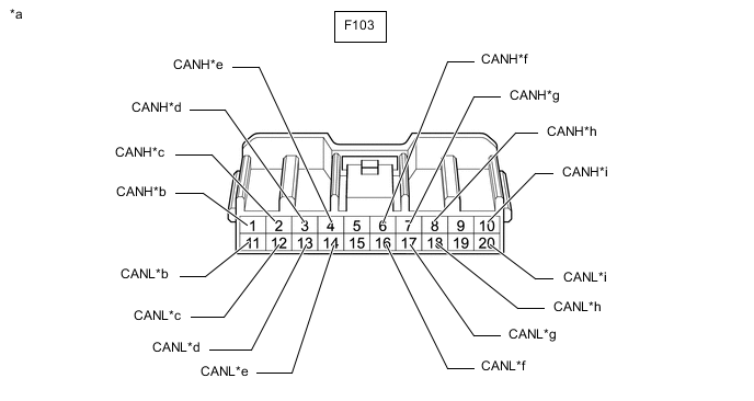
*a Front view of wire harness connector
(No. 4 CAN Junction Connector)
*b to No. 3 CAN Junction Connector
(for V Bus)
*c to Skid Control ECU (Brake Actuator Assembly)
(for V Bus)
*d to Air Conditioning Amplifier Assembly
(for V Bus)
*e to Airbag Sensor Assembly
(for V Bus)
*f to Radio and Display Receiver Assembly
(for Radio and Display Type)
(for V Bus)
*g to Certification ECU (Smart Key ECU Assembly)
(w/ Smart Entry and Start System)
(for V Bus)
*h to Combination Meter Assembly
(for V Bus)
*i to Network Gateway ECU
(w/ Blind Spot Monitor System or Parking Assist Monitor System)
(for V Bus)
- - -
Check the connection diagram of the components which are connected to the No. 4 CAN junction connector.
Terminal No. (Symbol) Wiring Color Connected to F103-1 (CANH) BR No. 3 CAN junction connector
(for V bus)
F103-11 (CANL) W F103-2 (CANH) GR Skid control ECU (brake actuator assembly)
(for V bus)
F103-12 (CANL) W F103-3 (CANH) BE Air conditioning amplifier assembly
(for V bus)
F103-13 (CANL) W F103-4 (CANH) Y Airbag sensor assembly
(for V bus)
F103-14 (CANL) W F103-6 (CANH) L Radio and display receiver assembly*1
(for V bus)
F103-16 (CANL) W F103-7 (CANH) G Certification ECU (smart key ECU assembly)*2
(for V bus)
F103-17 (CANL) W F103-8 (CANH) SB Combination meter assembly
(for V bus)
F103-18 (CANL) W F103-10 (CANH) P Network gateway ECU*3
(for V bus)
F103-20 (CANL) W
-
*1: for Radio and Display Type
-
*2: w/ Smart Entry and Start System
-
*3: w/ Blind Spot Monitor System or Parking Assist Monitor System
-
-
-
-
NO. 5 CAN JUNCTION CONNECTOR (for LHD)
-
Check the No. 5 CAN junction connector.
-
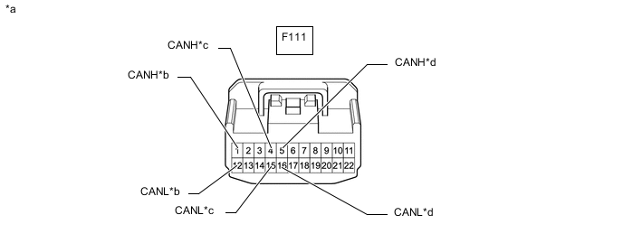
Connection diagram
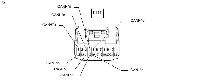
*a Front view of wire harness connector
(to No. 5 CAN Junction Connector)
*b to Multiplex Network Door ECU
(w/ Power Back Door System)
(for Sub Bus 1)
*c to Position Control ECU and Switch Assembly
(w/ Seat Position Memory System)
(for Sub Bus 1)
*d to Outer Mirror Control ECU Assembly (for Driver Side)
(w/ Seat Position Memory System)
(for Sub Bus 1)
*e to No. 6 CAN Junction Connector
(for Sub Bus 1)
- - -
Check the connection diagram of the components which are connected to the No. 5 CAN junction connector.
Terminal No. (Symbol) Wiring Color Connected to F111-1 (CANH) L Multiplex network door ECU*1
(for Sub bus 1)
F111-12 (CANL) W F111-3 (CANH) P Position control ECU and switch assembly*2
(for Sub bus 1)
F111-14 (CANL) W F111-4 (CANH) SB Outer mirror control ECU assembly (for driver side)*2
(for Sub bus 1)
F111-15 (CANL) W F111-5 (CANH) B No. 6 CAN junction connector
(for Sub bus 1)
F111-16 (CANL) W
-
*1: w/ Power Back Door System
-
*2: w/ Seat Position Memory System
-
-
-
-
NO. 6 CAN JUNCTION CONNECTOR (for LHD)
-
Check the No. 6 CAN junction connector.
-
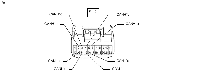
Connection diagram
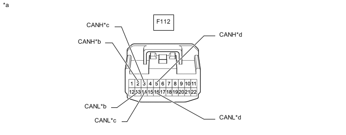
*a Front view of wire harness connector
(No. 6 CAN Junction Connector)
*b to Main Body ECU (Multiplex Network Body ECU)
(for Sub Bus 1)
*c to Outer Mirror Control ECU Assembly (for Front Passenger Side)
(w/ Seat Position Memory System)
(for Sub Bus 1)
*d to No. 5 CAN Junction Connector
(for Sub Bus 1)
-
Check the connection diagram of the components which are connected to the No. 6 CAN junction connector.
Terminal No. (Symbol) Wiring Color Connected to F112-2 (CANH) G Main body ECU (multiplex network body ECU)
(for Sub bus 1)
F112-13 (CANL) W F112-3 (CANH) LG Outer mirror control ECU assembly (for front passenger side)*
(for Sub bus 1)
F112-14 (CANL) W F112-5 (CANH) B No. 5 CAN junction connector
(for Sub bus 1)
F112-16 (CANL) W *: w/ Seat Position Memory System
-
-
-
NO. 1 CAN JUNCTION CONNECTOR (for RHD)
-
Check the No. 1 CAN junction connector.
Tech Tips
Connectors that connect to the CAN junction connector can be distinguished by the color of their CAN bus lines. When the connectors have been disconnected from the CAN junction connector, reconnecting the connectors to non-original positions on the CAN junction connector does not affect system performance. However, it is preferred to reconnect the connectors to their original positions to avoid negative effects on the wiring such as tension on the wiring harnesses, and to make future maintenance easier.
-
Connection diagram

*a Front view of wire harness connector
(No. 1 CAN Junction Connector)
*b to Driving Support ECU Assembly
(w/ Pre-crash Safety System)
(for Sub Bus 2)
*c to Lane Departure Warning Camera
(w/ Lane Departure Alert System)
(for Sub Bus 2)
*d to Network Gateway ECU
(w/ Blind Spot Monitor System or Parking Assist Monitor System)
(for Sub Bus 2)
*e to No. 2 CAN Junction Connector
(for Sub Bus 2)
- - -
Check the connection diagram of the components which are connected to the No. 1 CAN junction connector.
Terminal No. (Symbol) Wiring Color Connected to F104-1 (CANH) BR No. 2 CAN junction connector
(for Sub bus 2)
F104-2 (CANL) W F105-1 (CANH) L Network gateway ECU*1
(for Sub bus 2)
F105-2 (CANL) W F108-1 (CANH) R Lane departure warning camera*2
(for Sub bus 2)
F108-2 (CANL) W F110-1 (CANH) G Driving support ECU assembly*3
(for Sub bus 1)
F110-2 (CANL) W
-
*1: w/ Blind Spot Monitor System or Parking Assist Monitor System
-
*2: w/ Lane Departure Alert System
-
*3: w/ Pre-crash Safety System
-
-
-
-
NO. 2 CAN JUNCTION CONNECTOR (for RHD)
-
Check the No. 2 CAN junction connector.
Tech Tips
Connectors that connect to the CAN junction connector can be distinguished by the color of their CAN bus lines. When the connectors have been disconnected from the CAN junction connector, reconnecting the connectors to non-original positions on the CAN junction connector does not affect system performance. However, it is preferred to reconnect the connectors to their original positions to avoid negative effects on the wiring such as tension on the wiring harnesses, and to make future maintenance easier.
-
Connection diagram

*a Front view of wire harness connector
(No. 2 CAN Junction Connector)
*b to CAN Junction Terminal
(for Sub Bus 2)
*c to Blind Spot Monitor Sensor LH
(w/ Blind Spot Monitor System)
(for Sub Bus 2)
*d to Television Camera Assembly
(w/ Parking Assist Monitor System)
(for Sub Bus 2)
*e to No. 1 CAN Junction Connector
(for Sub Bus 2)
- - -
Check the connection diagram of the components which are connected to the No. 2 CAN junction connector.
Terminal No. (Symbol) Wiring Color Connected to M38-1 (CANH) BR No. 1 CAN junction connector
(for Sub bus 2)
M38-2 (CANL) W M39-1 (CANH) B Television camera assembly*1
(for Sub bus 2)
M39-2 (CANL) W M40-1 (CANH) GR Blind spot monitor sensor LH*2
(for Sub bus 2)
M40-2 (CANL) W M41-1 (CANH) B CAN junction terminal
(for Sub bus 2)
M41-2 (CANL) W
-
*1: w/ Parking Assist Monitor System
-
*2: w/ Blind Spot Monitor System
-
-
-
-
NO. 3 CAN JUNCTION CONNECTOR (for RHD)
-
Check the No. 3 CAN junction connector.
-
Connection diagram
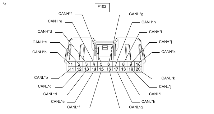
*a Front view of wire harness connector
(No. 3 CAN Junction Connector)
*b to No. 4 CAN Junction Connector
(for V Bus)
*c to ECM
(for V Bus)
*d to Air Conditioning Amplifier Assembly
(for V Bus)
*e to Airbag Sensor Assembly
(for V Bus)
*f to Clearance Warning ECU Assembly
(w/ Toyota Parking Assist-sensor System)
(for V Bus)
*g to Main Body ECU (Multiplex Network Body ECU)
(for V Bus)
*h to Certification ECU (Smart Key ECU Assembly)
(w/ Smart Entry and Start System)
(for V Bus)
*i to 4WD ECU Assembly
(for AWD)
(for V Bus)
*j to Headlight Leveling ECU Assembly
(w/ Automatic Headlight Beam Level Control System)
(for V Bus)
*k to Network Gateway ECU
(w/ Blind Spot Monitor System or Parking Assist Monitor System)
(for V Bus)
- - -
Check the connection diagram of the components which are connected to the No. 3 CAN junction connector.
Terminal No. (Symbol) Wiring Color Connected to F102-1 (CANH) BR No. 4 CAN junction connector
(for V bus)
F102-11 (CANL) W F102-2 (CANH) B ECM
(for V bus)
F102-12 (CANL) W F102-3 (CANH) BE Air conditioning amplifier assembly
(for V bus)
F102-13 (CANL) W F102-4 (CANH) Y Airbag sensor assembly
(for V bus)
F102-14 (CANL) W F102-5 (CANH) LG Clearance warning ECU assembly*1
(for V bus)
F102-15 (CANL) W F102-6 (CANH) R Main body ECU (multiplex network body ECU)
(for V bus)
F102-16 (CANL) W F102-7 (CANH) G Certification ECU (smart key ECU assembly)*2
(for V bus)
F102-17 (CANL) W F102-8 (CANH) L 4WD ECU assembly*3
(for V bus)
F102-18 (CANL) W F102-9 (CANH) GR Headlight leveling ECU assembly*4
(for V bus)
F102-19 (CANL) W F102-10 (CANH) P Network gateway ECU*5
(for V bus)
F102-20 (CANL) W
-
*1: w/ Toyota Parking Assist-sensor System
-
*2: w/ Smart Entry and Start System
-
*3: for AWD
-
*4: w/ Automatic Headlight Beam Level Control System
-
*5: w/ Blind Spot Monitor System or Parking Assist Monitor System
-
-
-
-
NO. 4 CAN JUNCTION CONNECTOR (for RHD)
-
Check the No. 4 CAN junction connector.
-
Connection diagram
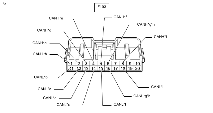
*a Front view of wire harness connector
(No. 4 CAN Junction Connector)
*b to No. 3 CAN Junction Connector
(for V Bus)
*c to Skid Control ECU (Brake Actuator Assembly)
(for V Bus)
*d to DLC3
(for V Bus)
*e to Steering Sensor
(for V Bus)
*f to Power Steering ECU Assembly
(for V Bus)
*g to Navigation Receiver Assembly
(for Navigation Receiver Type)
(for V Bus)
*h to Radio and Display Receiver Assembly
(for Radio and Display Type)
(for V Bus)
*i to Combination Meter Assembly
(for V Bus)
- - -
Check the connection diagram of the components which are connected to the No. 4 CAN junction connector.
Terminal No. (Symbol) Wiring Color Connected to F103-1 (CANH) BR No. 3 CAN junction connector
(for V bus)
F103-11 (CANL) W F103-2 (CANH) GR Skid control ECU (brake actuator assembly)
(for V bus)
F103-12 (CANL) W F103-3 (CANH) V DLC3
(for V bus)
F103-13 (CANL) W F103-4 (CANH) BE Steering sensor
(for V bus)
F103-14 (CANL) W F103-5 (CANH) P Power steering ECU assembly
(for V bus)
F103-15 (CANL) W F103-6 (CANH) L Navigation receiver assembly*1
(for V bus)
F103-16 (CANL) W F103-6 (CANH) L Radio and display receiver assembly*2
(for V bus)
F103-16 (CANL) W F103-8 (CANH) SB Combination meter assembly
(for V bus)
F103-18 (CANL) W
-
*1: for Navigation Receiver Type
-
*2: for Radio and Display Type
-
-
-
-
NO. 5 CAN JUNCTION CONNECTOR (for RHD)
-
Check the No. 5 CAN junction connector.
-
Connection diagram
*a Front view of wire harness connector
(to No. 5 CAN Junction Connector)
*b to Multiplex Network Door ECU
(w/ Power Back Door System)
(for Sub Bus 1)
*c to Outer Mirror Control ECU Assembly (for Front Passenger Side)
(w/ Seat Position Memory System)
(for Sub Bus 1)
*d to No. 6 CAN Junction Connector
(for Sub Bus 1)
-
Check the connection diagram of the components which are connected to the No. 5 CAN junction connector.
Terminal No. (Symbol) Wiring Color Connected to F111-1 (CANH) L Multiplex network door ECU*1
(for Sub bus 1)
F111-12 (CANL) W F111-4 (CANH) SB Outer mirror control ECU assembly (for front passenger side)*2
(for Sub bus 1)
F111-15 (CANL) W F111-5 (CANH) B No. 6 CAN junction connector
(for Sub bus 1)
F111-16 (CANL) W
-
*1: w/ Power Back Door System
-
*2: w/ Seat Position Memory System
-
-
-
-
NO. 6 CAN JUNCTION CONNECTOR (for RHD)
-
Check the No. 6 CAN junction connector.
-
Connection diagram
*a Front view of wire harness connector
(No. 6 CAN Junction Connector)
*b to Main Body ECU (Multiplex Network Body ECU)
(for Sub Bus 1)
*c to Outer Mirror Control ECU Assembly (for Driver Side)
(w/ Seat Position Memory System)
(for Sub Bus 1)
*d to Position Control ECU and Switch Assembly
(w/ Seat Position Memory System)
(for Sub Bus 1)
*e to No. 5 CAN Junction Connector
(for Sub Bus 1)
- - -
Check the connection diagram of the components which are connected to the No. 6 CAN junction connector.
Terminal No. (Symbol) Wiring Color Connected to F112-2 (CANH) G Main body ECU (multiplex network body ECU)
(for Sub bus 1)
F112-13 (CANL) W F112-3 (CANH) LG Outer mirror control ECU assembly (for driver side)*
(for Sub bus 1)
F112-14 (CANL) W F112-4 (CANH) P Position control ECU and switch assembly*
(for Sub bus 1)
F112-15 (CANL) W F112-5 (CANH) B No. 5 CAN junction connector
(for Sub bus 1)
F112-16 (CANL) W *: w/ Seat Position Memory System
-
-
-
CAN JUNCTION TERMINAL
-
Check the CAN junction terminal.
-
Connection diagram

*a Front view of wire harness connector
(to CAN Junction Terminal)
*b to No. 2 CAN Junction Connector
(for Sub Bus 2)
-
Check the connection diagram of the components which are connected to the CAN junction terminal.
Terminal No. (Symbol) Wiring Color Connected to M42-3 (CANH) B No. 2 CAN junction connector
(for Sub bus 2)
M42-2 (CANL) W
-
-
-
DLC3
-
Disconnect the cable from the negative (-) battery terminal.
-
Measure the resistance according to the value(s) in the table below.

*1 DLC3 - -
-
-
ECM (for 1AR-FE)
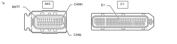
*a Component without harness connected
(ECM)
- -
-
Disconnect the cable from the negative (-) battery terminal.
-
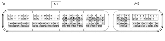
Disconnect the A43 and C1 ECM connectors.
*a Front view of wire harness connector
(to ECM)
- - -
Measure the resistance according to the value(s) in the table below.
-
-
ECM (for 2GR-FE)
*a Component without harness connected
(ECM)
- -
-
Disconnect the cable from the negative (-) battery terminal.
-
Disconnect the A43 and C1 ECM connectors.
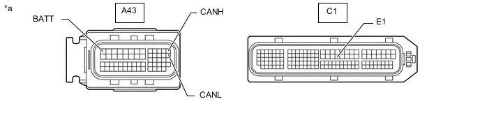
*a Front view of wire harness connector
(to ECM)
- - -
Measure the resistance according to the value(s) in the table below.
-
-
COMBINATION METER ASSEMBLY
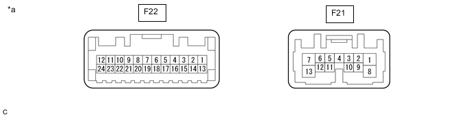
*a Component without harness connected
(Combination Meter Assembly)
- -
-
Disconnect the cable from the negative (-) battery terminal.
-
Disconnect the F22 combination meter assembly connector.

*a Front view of wire harness connector
(to Combination Meter Assembly)
- - -
Measure the resistance according to the value(s) in the table below.
-
-
INSTRUMENT PANEL JUNCTION BLOCK ASSEMBLY AND MAIN BODY ECU (MULTIPLEX NETWORK BODY ECU)
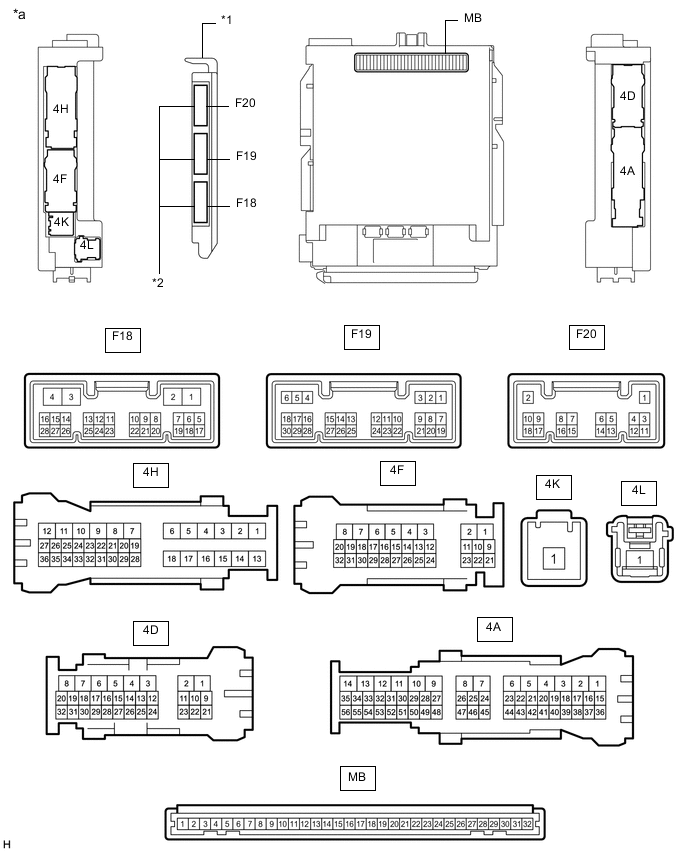
*1 Main Body ECU (Multiplex Network Body ECU) *2 3 Connectors *a Component without harness connected
(Instrument Panel Junction Block Assembly and Main Body ECU (Multiplex Network Body ECU))
- - 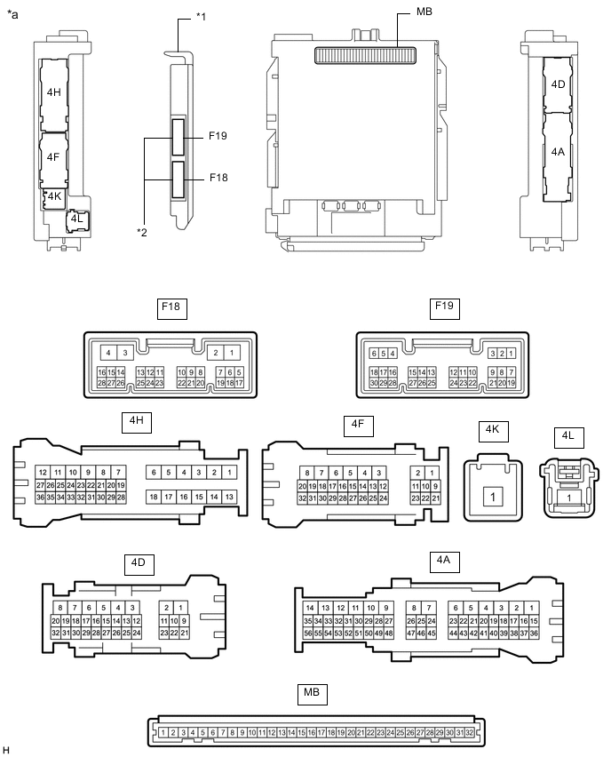
*1 Main Body ECU (Multiplex Network Body ECU) *2 2 Connectors *a Component without harness connected
(Instrument Panel Junction Block Assembly and Main Body ECU (Multiplex Network Body ECU))
- -
-
Disconnect the cable from the negative (-) battery terminal.
-
Disconnect the F18 and F19 main body ECU (multiplex network body ECU) connectors.
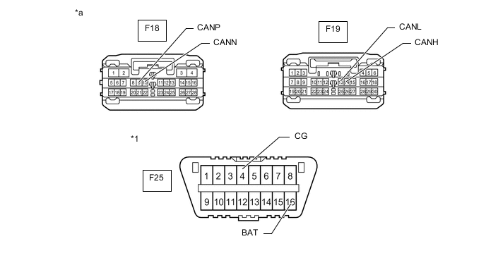
*1 DLC3 - - *a Front view of wire harness connector
(to Main Body ECU (Multiplex Network Body ECU))
- - -
Measure the resistance according to the value(s) in the table below.
-
-
SKID CONTROL ECU (BRAKE ACTUATOR ASSEMBLY)

*a Component without harness connected
(Skid Control ECU (Brake Actuator Assembly))
- -
-
Disconnect the cable from the negative (-) battery terminal.
-
Disconnect the A47 skid control ECU (brake actuator assembly) connector.

*a Front view of wire harness connector
(to Skid Control ECU (Brake Actuator Assembly))
- - -
Measure the resistance according to the value(s) in the table below.
-
-
STEERING SENSOR

*a Component without harness connected
(Steering Sensor)
- -
-
Disconnect the cable from the negative (-) battery terminal.
-
Disconnect the F58 steering sensor connector.

*a Front view of wire harness connector
(to Steering Sensor)
- - -
Measure the resistance according to the value(s) in the table below.
-
-
POWER STEERING ECU ASSEMBLY
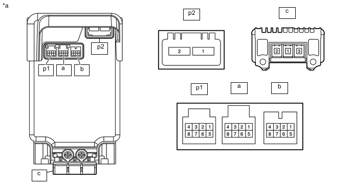
*a Component without harness connected
(Power Steering ECU Assembly)
- -
-
Disconnect the cable from the negative (-) battery terminal.
-
Disconnect the p1 and p2 power steering ECU assembly connectors.
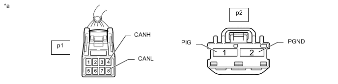
*a Front view of wire harness connector
(to Power Steering ECU Assembly)
- - -
Measure the resistance according to the value(s) in the table below.
-
-
AIRBAG SENSOR ASSEMBLY
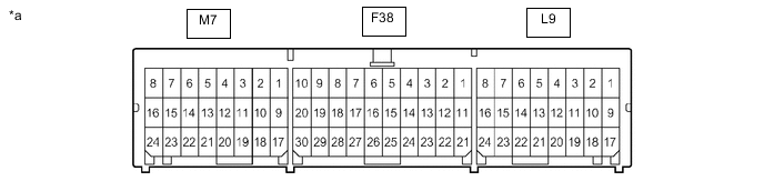
*a Component without harness connected
(Airbag Sensor Assembly)
- -
-
Disconnect the cable from the negative (-) battery terminal.
-
Disconnect the F38 airbag sensor assembly connector.
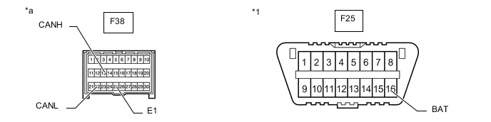
*1 DLC3 - - *a Front view of wire harness connector
(to Airbag Sensor Assembly)
- - -
Measure the resistance according to the value(s) in the table below.
-
-
AIR CONDITIONING AMPLIFIER ASSEMBLY
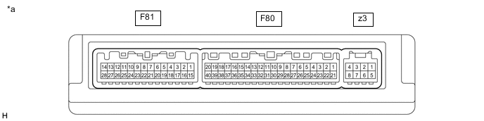
*a Component without harness connected
(Air Conditioning Amplifier Assembly)
- -
-
Disconnect the cable from the negative (-) battery terminal.
-
Disconnect the F80 air conditioning amplifier assembly connector.

*a Front view of wire harness connector
(to Air Conditioning Amplifier Assembly)
- - -
Measure the resistance according to the value(s) in the table below.
-
-
CERTIFICATION ECU (SMART KEY ECU ASSEMBLY) (w/ Smart Entry and Start System)
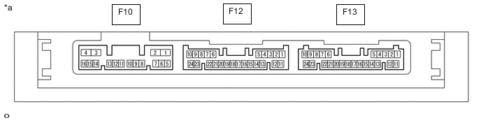
*a Component without harness connected
(Certification ECU (Smart Key ECU Assembly))
- -
-
Disconnect the cable from the negative (-) battery terminal.
-
Disconnect the F13 certification ECU (smart key ECU assembly) connector.

*a Front view of wire harness connector
(to Certification ECU (Smart Key ECU Assembly))
- - -
Measure the resistance according to the value(s) in the table below.
-
-
NAVIGATION RECEIVER ASSEMBLY (for Navigation Receiver Type)
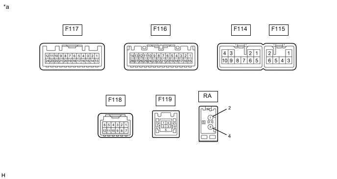
*a Component without harness connected
(Navigation Receiver Assembly)
- -
-
Disconnect the cable from the negative (-) battery terminal.
-
Disconnect the F114 and F116 navigation receiver assembly connectors.

*a Front view of wire harness connector
(to Navigation Receiver Assembly)
- - -
Measure the resistance according to the value(s) in the table below.
-
-
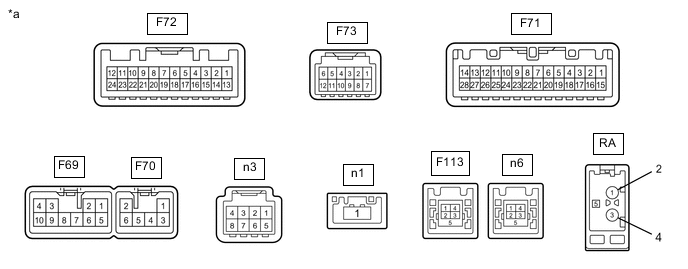
RADIO AND DISPLAY RECEIVER ASSEMBLY (for Radio and Display Type)
*a Component without harness connected
(Radio and Display Receiver Assembly)
- -
-
Disconnect the cable from the negative (-) battery terminal.
-
Disconnect the F69 and F71 radio and display receiver assembly connectors.
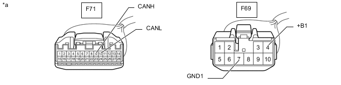
*a Front view of wire harness connector
(to Radio and Display Receiver Assembly)
- - -
Measure the resistance according to the value(s) in the table below.
-
-
NETWORK GATEWAY ECU (w/ Blind Spot Monitor System or Parking Assist Monitor System)

*a Component without harness connected
(Network Gateway ECU)
- -
-
Disconnect the cable from the negative (-) battery terminal.
-
Disconnect the F85 network gateway ECU connector.

*a Front view of wire harness connector
(to Network Gateway ECU)
- - -
Measure the resistance according to the value(s) in the table below.
-
-
CLEARANCE WARNING ECU ASSEMBLY (w/ Toyota Parking Assist-sensor System)

*a Component without harness connected
(Clearance Warning ECU Assembly)
- -
-
Disconnect the cable from the negative (-) battery terminal.
-
Disconnect the F87 clearance warning ECU assembly connector.
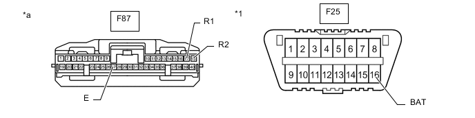
*1 DLC3 - - *a Front view of wire harness connector
(to Clearance Warning ECU Assembly)
- - -
Measure the resistance according to the value(s) in the table below.
-
-
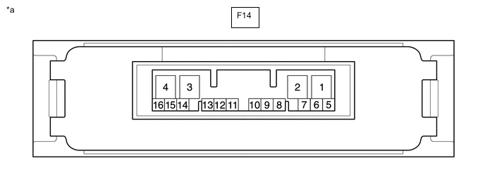
4WD ECU ASSEMBLY (for AWD)
*a Component without harness connected
(4WD ECU Assembly)
- -
-
Disconnect the cable from the negative (-) battery terminal.
-
Disconnect the F14 4WD ECU assembly connector.
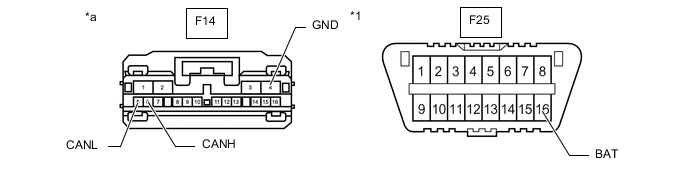
*1 DLC3 - - *a Front view of wire harness connector
(to 4WD ECU Assembly)
- - -
Measure the resistance according to the value(s) in the table below.
-
-
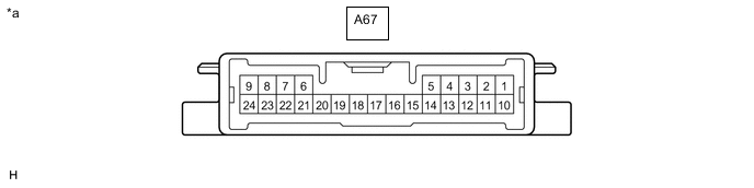
HEADLIGHT LEVELING ECU ASSEMBLY (w/ Automatic Headlight Beam Level Control System)
*a Component without harness connected
(Headlight Leveling ECU Assembly)
- -
-
Disconnect the cable from the negative (-) battery terminal.
-
Disconnect the A67 headlight leveling ECU assembly connector.
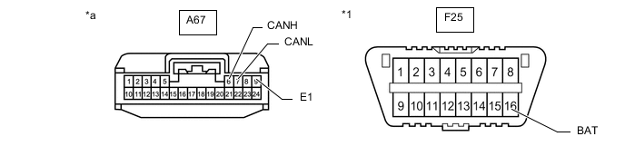
*1 DLC3 - - *a Front view of wire harness connector
(to Headlight Leveling ECU Assembly)
- - -
Measure the resistance according to the value(s) in the table below.
-
-
OUTER MIRROR CONTROL ECU ASSEMBLY (for Driver Side) (w/ Seat Position Memory System)

*A for LHD *B for RHD *a Component without harness connected
(Outer Mirror Control ECU Assembly (for Driver Side))
- -
-
Disconnect the cable from the negative (-) battery terminal.
-
Disconnect the H2 or I2 outer mirror control ECU assembly (for driver side) connector.

*A for LHD *B for RHD *a Front view of wire harness connector
(to Outer Mirror Control ECU Assembly (for Driver Side))
- - -
Measure the resistance according to the value(s) in the table below.
-
-
OUTER MIRROR CONTROL ECU ASSEMBLY (for Front Passenger Side) (w/ Seat Position Memory System)

*A for LHD *B for RHD *a Component without harness connected
(Outer Mirror Control ECU Assembly (for Front Passenger Side))
- -
-
Disconnect the cable from the negative (-) battery terminal.
-
Disconnect the H2 or I2 outer mirror control ECU assembly (for front passenger side) connector.

*A for LHD *B for RHD *a Front view of wire harness connector
(to Outer Mirror Control ECU Assembly (for Front Passenger Side))
- - -
Measure the resistance according to the value(s) in the table below.
-
-
POSITION CONTROL ECU AND SWITCH ASSEMBLY (for LHD w/ Seat Position Memory System)

*a Component without harness connected
(Position Control ECU and Switch Assembly)
- -
-
Disconnect the cable from the negative (-) battery terminal.
-
Disconnect the e6 and e7 position control ECU and switch assembly connectors.
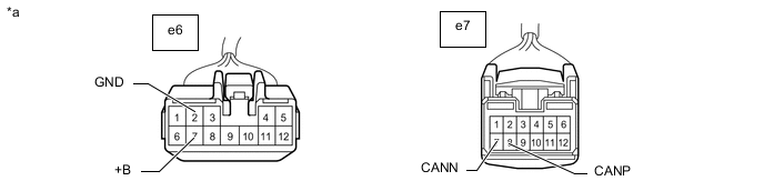
*a Front view of wire harness connector
(to Position Control ECU and Switch Assembly)
- - -
Measure the resistance according to the value(s) in the table below.
-
-
POSITION CONTROL ECU AND SWITCH ASSEMBLY (for RHD w/ Seat Position Memory System)

*a Component without harness connected
(Position Control ECU and Switch Assembly)
- -
-
Disconnect the cable from the negative (-) battery terminal.
-
Disconnect the d6 and d7 position control ECU and switch assembly connectors.
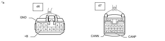
*a Front view of wire harness connector
(to Position Control ECU and Switch Assembly)
- - -
Measure the resistance according to the value(s) in the table below.
-
-
MULTIPLEX NETWORK DOOR ECU (w/ Power Back Door System)
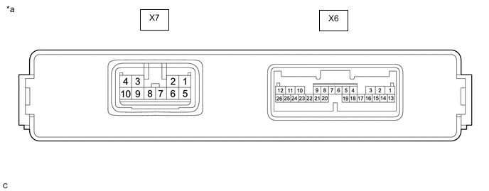
*a Component without harness connected
(Multiplex Network Door ECU)
- -
-
Disconnect the cable from the negative (-) battery terminal.
-
Disconnect the X6 and X7 multiplex network door ECU connectors.
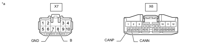
*a Front view of wire harness connector
(to Multiplex Network Door ECU)
- - -
Measure the resistance according to the value(s) in the table below.
-
-
BLIND SPOT MONITOR SENSOR LH (w/ Blind Spot Monitor System)

*a Component without harness connected
(Blind Spot Monitor Sensor LH)
- -
-
Disconnect the cable from the negative (-) battery terminal.
-
Disconnect the M31 blind spot monitor sensor LH connector.
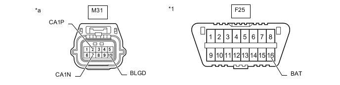
*1 DLC3 - - *a Front view of wire harness connector
(to Blind Spot Monitor Sensor LH)
- - -
Measure the resistance according to the value(s) in the table below.
-
-
DRIVING SUPPORT ECU ASSEMBLY (w/ Pre-crash Safety System)

*a Component without harness connected
(Driving Support ECU assembly)
- -
-
Disconnect the cable from the negative (-) battery terminal.
-
Disconnect the F84 driving support ECU assembly connector.
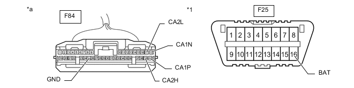
*1 DLC3 - - *a Front view of wire harness connector
(to Driving Support ECU Assembly)
- - -
Measure the resistance according to the value(s) in the table below.
-
-
MILLIMETER WAVE RADAR SENSOR ASSEMBLY (w/ Pre-crash Safety System)

*a Component without harness connected
(Millimeter Wave Radar Sensor Assembly)
- -
-
Disconnect the cable from the negative (-) battery terminal.
-
Disconnect the A3 millimeter wave radar sensor assembly connector.
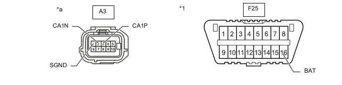
*1 DLC3 - - *a Front view of wire harness connector
(to Millimeter Wave Radar Sensor Assembly)
- - -
Measure the resistance according to the value(s) in the table below.
-
-
LANE DEPARTURE WARNING CAMERA (w/ Lane Departure Alert System)
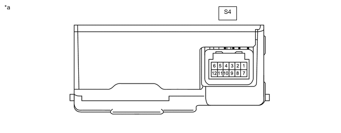
*a Component without harness connected
(Lane Departure Warning Camera)
- -
-
Disconnect the cable from the negative (-) battery terminal.
-
Disconnect the S4 lane departure warning camera connector.
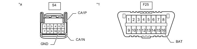
*1 DLC3 - - *a Front view of wire harness connector
(to Lane Departure Warning Camera)
- - -
Measure the resistance according to the value(s) in the table below.
-
-
TELEVISION CAMERA ASSEMBLY (w/ Parking Assist Monitor System)
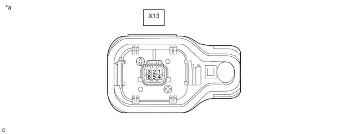
*a Component without harness connected
(Television Camera Assembly)
- -
-
Disconnect the cable from the negative (-) battery terminal.
-
Disconnect the X13 television camera assembly connector.
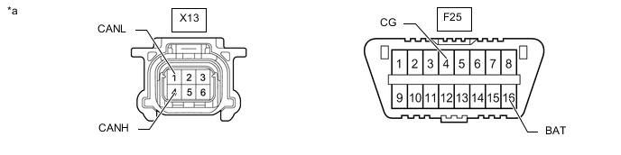
*a Front view of wire harness connector
(to Television Camera Assembly)
- - -
Measure the resistance according to the value(s) in the table below.
-