LIN COMMUNICATION SYSTEM, Diagnostic DTC:B2325
| DTC Code | DTC Name |
|---|---|
| B2325 | LIN Communication Bus Malfunction |
DESCRIPTION
The main body ECU (multiplex network body ECU) monitors communication between all the ECUs connected to the door bus lines. When the main body ECU (multiplex network body ECU) detects errors in communication with all the ECUs connected to the door bus lines at 2.6-second intervals and 3 times in a row, DTC B2325 will be stored.
| DTC No. | Detection Item | DTC Detection Condition | Trouble Area |
|---|---|---|---|
| B2325 | LIN Communication Bus Malfunction | Main body ECU (multiplex network body ECU) detects errors in communication with the ECUs connected to the door bus lines 3 times in a row. |
|
-
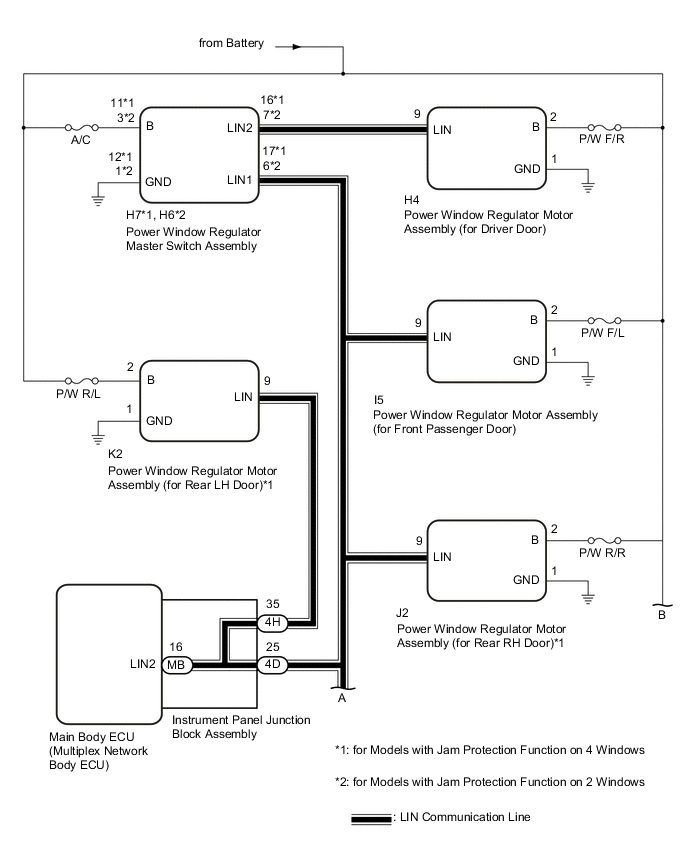
*1: for Models with Jam Protection Function on 4 Windows
-
*2: w/ Sliding Roof System
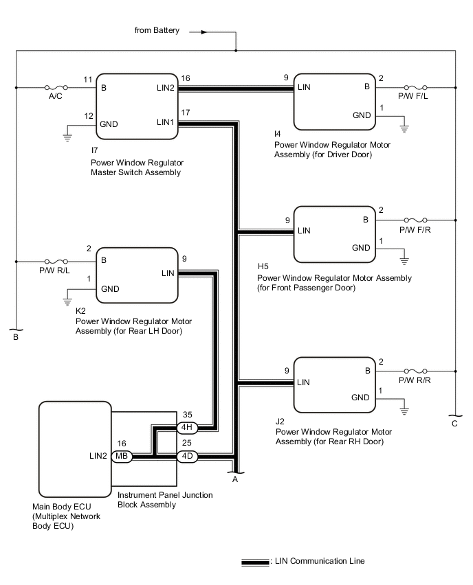
WIRING DIAGRAM
-
for LHD

-
for RHD

CAUTION / NOTICE / HINT
Note
-
When a power window regulator motor assembly is replaced or removed and reinstalled, it requires initialization.
-
When the sliding roof ECU (sliding roof drive gear sub-assembly) is replaced or removed and reinstalled, it requires initialization (w/ Sliding Roof System).
-
Before performing the inspection, check that DTC B1206, B1273, B2321, B2322, B2323 or B2324 is not output.
-
If the main body ECU (multiplex network body ECU) is replaced, refer to Service Bulletin.*
-
*: Smart Entry and Start System
-
As the door control battery is installed between the vehicle battery and main body ECU (multiplex network body ECU), first perform the inspections in On-Vehicle Inspection to confirm that there are no malfunctions in the power source circuit for the main body ECU (multiplex network body ECU) before performing this troubleshooting procedure.*
-
*: for LHD
PROCEDURE
-
CONFIRM MODEL
-
Choose the model to be inspected.
Result Result Proceed to for Models with Jam Protection Function on 4 Windows A for Models with Jam Protection Function on 2 Windows B
B 
INSPECT POWER WINDOW REGULATOR MASTER SWITCH ASSEMBLY Click here
A 
-
-
INSPECT POWER WINDOW REGULATOR MASTER SWITCH ASSEMBLY
-
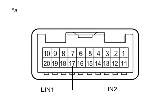
*a Component without harness connected
(Power Window Regulator Master Switch Assembly)
Remove the power window regulator master switch assembly.
-
Measure the resistance according to the value(s) in the table below.
Standard Resistance Tester Connection Condition Specified Condition 16 (LIN2) - 17 (LIN1) Always Below 1 Ω Result Proceed to OK NG
NG 
REPLACE POWER WINDOW REGULATOR MASTER SWITCH ASSEMBLY
OK
-
-
CHECK HARNESS AND CONNECTOR (POWER WINDOW REGULATOR MASTER SWITCH ASSEMBLY - POWER WINDOW REGULATOR MOTOR ASSEMBLY (for Driver Door))
-
for LHD
-
Disconnect the I4 power window regulator motor assembly (for driver door) connector.
-
Measure the resistance according to the value(s) in the table below.
Note
Make sure that each ECU is in sleep mode before performing the inspection. To enter sleep mode, turn the ignition switch from ON to off and wait for 180 seconds or more without operating any switches.
Standard Resistance Tester Connection Condition Specified Condition I7-16 (LIN2) - I4-9 (LIN) Ignition switch off Below 1 Ω I7-16 (LIN2) or I4-9 (LIN) - Body ground Ignition switch off 10 kΩ or higher
-
-
for RHD
-
Disconnect the H4 power window regulator motor assembly (for driver door) connector.
-
Measure the resistance according to the value(s) in the table below.
Note
Make sure that each ECU is in sleep mode before performing the inspection. To enter sleep mode, turn the ignition switch from ON to off and wait for 180 seconds or more without operating any switches.
Standard Resistance Tester Connection Condition Specified Condition H7-16 (LIN2) - H4-9 (LIN) Ignition switch off Below 1 Ω H7-16 (LIN2) or H4-9 (LIN) - Body ground Ignition switch off 10 kΩ or higher
Result Proceed to OK NG -
NG
REPAIR OR REPLACE HARNESS OR CONNECTOR
OK
-
-
INSPECT INSTRUMENT PANEL JUNCTION BLOCK ASSEMBLY
-
Remove the instrument panel junction block assembly.
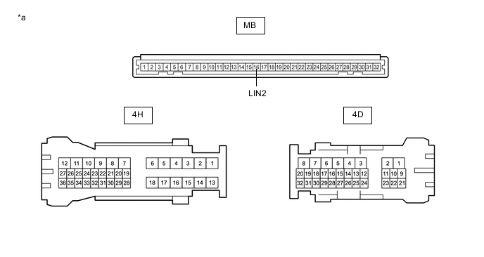
*a Component without harness connected
(Instrument Panel Junction Block Assembly)
- - -
Remove the main body ECU (multiplex network body ECU) from the instrument panel junction block assembly.
-
Measure the resistance according to the value(s) in the table below.
Tech Tips
This inspection is to check the LIN communication line in the instrument panel junction block assembly that connects the wire harness to the built-in main body ECU (multiplex network body ECU).
Standard Resistance Tester Connection Condition Specified Condition 4D-25 - MB-16 (LIN2) Always Below 1 Ω 4H-35 - MB-16 (LIN2) Always Below 1 Ω Result Proceed to OK NG
NG
REPLACE INSTRUMENT PANEL JUNCTION BLOCK ASSEMBLY Click here
OK
-
-
CHECK HARNESS AND CONNECTOR (INSTRUMENT PANEL JUNCTION BLOCK ASSEMBLY - EACH ECU)
-
for LHD
-
Disconnect the H5 power window regulator motor assembly (for front passenger door) connector.
-
Disconnect the K2 power window regulator motor assembly (for rear LH door) connector.
-
Disconnect the J2 power window regulator motor assembly (for rear RH door) connector.
-
Disconnect the I7 power window regulator master switch assembly connector.
-
Disconnect the S5 sliding roof ECU (sliding roof drive gear sub-assembly) connector.*
-
*: w/ Sliding Roof System
-
-
Measure the resistance according to the value(s) in the table below.
Note
Make sure that each ECU is in sleep mode before performing the inspection. To enter sleep mode, turn the ignition switch from ON to off and wait for 180 seconds or more without operating any switches.
Standard Resistance Tester Connection Condition Specified Condition 4D-25 - I7-17 (LIN1) Ignition switch off Below 1 Ω 4D-25 - S5-11 (MPX1)* Ignition switch off Below 1 Ω 4D-25 - H5-9 (LIN) Ignition switch off Below 1 Ω 4D-25 - J2-9 (LIN) Ignition switch off Below 1 Ω 4H-35 - K2-9 (LIN) Ignition switch off Below 1 Ω I7-17 (LIN1) - Body ground Ignition switch off 10 kΩ or higher S5-11 (MPX1) - Body ground* Ignition switch off 10 kΩ or higher 4D-25 - Body ground Ignition switch off 10 kΩ or higher 4H-35 - Body ground Ignition switch off 10 kΩ or higher H5-9 (LIN) - Body ground Ignition switch off 10 kΩ or higher J2-9 (LIN) - Body ground Ignition switch off 10 kΩ or higher K2-9 (LIN) - Body ground Ignition switch off 10 kΩ or higher
-
*: w/ Sliding Roof System
-
-
-
for RHD
-
Disconnect the I5 power window regulator motor assembly (for front passenger door) connector.
-
Disconnect the K2 power window regulator motor assembly (for rear LH door) connector.
-
Disconnect the J2 power window regulator motor assembly (for rear RH door) connector.
-
Disconnect the H7 power window regulator master switch assembly connector.
-
Disconnect the S5 sliding roof ECU (sliding roof drive gear sub-assembly) connector.*
-
*: w/ Sliding Roof System
-
-
Measure the resistance according to the value(s) in the table below.
Note
Make sure that each ECU is in sleep mode before performing the inspection. To enter sleep mode, turn the ignition switch from ON to off and wait for 180 seconds or more without operating any switches.
Standard Resistance Tester Connection Condition Specified Condition 4D-25 - H7-17 (LIN1) Ignition switch off Below 1 Ω 4D-25 - S5-11 (MPX1)* Ignition switch off Below 1 Ω 4D-25 - J2-9 (LIN) Ignition switch off Below 1 Ω 4D-25 - I5-9 (LIN) Ignition switch off Below 1 Ω 4H-35 - K2-9 (LIN) Ignition switch off Below 1 Ω H7-17 (LIN1) - Body ground Ignition switch off 10 kΩ or higher S5-11 (MPX1) - Body ground* Ignition switch off 10 kΩ or higher 4D-25 - Body ground Ignition switch off 10 kΩ or higher 4H-35 - Body ground Ignition switch off 10 kΩ or higher J2-9 (LIN) - Body ground Ignition switch off 10 kΩ or higher I5-9 (LIN) - Body ground Ignition switch off 10 kΩ or higher K2-9 (LIN) - Body ground Ignition switch off 10 kΩ or higher
-
*: w/ Sliding Roof System
-
Result Proceed to OK NG -
NG
REPAIR OR REPLACE HARNESS OR CONNECTOR
OK
-
-
CHECK POWER WINDOW REGULATOR MOTOR ASSEMBLY (for Rear LH Door)
-
for LHD
-
Reconnect the 4D and 4H instrument panel junction block assembly connectors.
-
Reconnect the I4 power window regulator motor assembly (for driver door) connector.
-
Reconnect the H5 power window regulator motor assembly (for front passenger door) connector.
-
Reconnect the J2 power window regulator motor assembly (for rear RH door) connector.
-
Reconnect the I7 power window regulator master switch assembly connector.
-
Reconnect the S5 sliding roof ECU (sliding roof drive gear sub-assembly) connector.*
-
*: w/ Sliding Roof System
-
-
Clear the DTCs.
Body Electrical > Main Body > Clear DTCs -
After 10 seconds have elapsed, check if the same DTC is output again.
Body Electrical > Main Body > Trouble Codes
-
-
for RHD
-
Reconnect the 4D and 4H instrument panel junction block assembly connectors.
-
Reconnect the H4 power window regulator motor assembly (for driver door) connector.
-
Reconnect the I5 power window regulator motor assembly (for front passenger door) connector.
-
Reconnect the J2 power window regulator motor assembly (for rear RH door) connector.
-
Reconnect the H7 power window regulator master switch assembly connector.
-
Reconnect the S5 sliding roof ECU (sliding roof drive gear sub-assembly) connector.*
-
*: w/ Sliding Roof System
-
-
Clear the DTCs.
Body Electrical > Main Body > Clear DTCs -
After 10 seconds have elapsed, check if the same DTC is output again.
Body Electrical > Main Body > Trouble Codes
Result Result Proceed to DTC B2325 is output A DTC B2325 is not output B -
B
REPLACE POWER WINDOW REGULATOR MOTOR ASSEMBLY (for Rear LH Door) Click here
A
-
-
CHECK POWER WINDOW REGULATOR MASTER SWITCH ASSEMBLY
-
for LHD
-
Reconnect the K2 power window regulator motor assembly (for rear LH door) connector.
-
Disconnect the I7 power window regulator master switch assembly connector.
-
Clear the DTCs.
Body Electrical > Main Body > Clear DTCs -
After 10 seconds have elapsed, check if the same DTC is output again.
Body Electrical > Main Body > Trouble Codes
-
-
for RHD
-
Reconnect the K2 power window regulator motor assembly (for rear LH door) connector.
-
Disconnect the H7 power window regulator master switch assembly connector.
-
Clear the DTCs.
Body Electrical > Main Body > Clear DTCs -
After 10 seconds have elapsed, check if the same DTC is output again.
Body Electrical > Main Body > Trouble Codes
Result Result Proceed to DTC B2325 is output A DTC B2325 is not output B -
B
REPLACE POWER WINDOW REGULATOR MASTER SWITCH ASSEMBLY Click here
A
-
-
CHECK POWER WINDOW REGULATOR MOTOR ASSEMBLY (for Rear RH Door)
-
for LHD
-
Reconnect the I7 power window regulator master switch assembly connector.
-
Disconnect the J2 power window regulator motor assembly (for rear RH door) connector.
-
Clear the DTCs.
Body Electrical > Main Body > Clear DTCs -
After 10 seconds have elapsed, check if the same DTC is output again.
Body Electrical > Main Body > Trouble Codes
-
-
for RHD
-
Reconnect the H7 power window regulator master switch assembly connector.
-
Disconnect the J2 power window regulator motor assembly (for rear RH door) connector.
-
Clear the DTCs.
Body Electrical > Main Body > Clear DTCs -
After 10 seconds have elapsed, check if the same DTC is output again.
Body Electrical > Main Body > Trouble Codes
Result Result Proceed to DTC B2325 is output A DTC B2325 is not output B -
B
REPLACE POWER WINDOW REGULATOR MOTOR ASSEMBLY (for Rear RH Door) Click here
A
-
-
CHECK POWER WINDOW REGULATOR MOTOR ASSEMBLY (for Driver Door)
-
for LHD
-
Reconnect the J2 power window regulator motor assembly (for rear RH door) connector.
-
Disconnect the I4 power window regulator motor assembly (for driver door) connector.
-
Clear the DTCs.
Body Electrical > Main Body > Clear DTCs -
After 10 seconds have elapsed, check if the same DTC is output again.
Body Electrical > Main Body > Trouble Codes
-
-
for RHD
-
Reconnect the J2 power window regulator motor assembly (for rear RH door) connector.
-
Disconnect the H4 power window regulator motor assembly (for driver door) connector.
-
Clear the DTCs.
Body Electrical > Main Body > Clear DTCs -
After 10 seconds have elapsed, check if the same DTC is output again.
Body Electrical > Main Body > Trouble Codes
Result Result Proceed to DTC B2325 is output A DTC B2325 is not output B -
B
REPLACE POWER WINDOW REGULATOR MOTOR ASSEMBLY (for Driver Door) Click here
A
-
-
CHECK POWER WINDOW REGULATOR MOTOR ASSEMBLY (for Front Passenger Door)
-
for LHD
-
Reconnect the I4 power window regulator motor assembly (for driver door) connector.
-
Disconnect the H5 power window regulator motor assembly (for front passenger door) connector.
-
Clear the DTCs.
Body Electrical > Main Body > Clear DTCs -
After 10 seconds have elapsed, check if the same DTC is output again.
Body Electrical > Main Body > Trouble Codes
-
-
for RHD
-
Reconnect the H4 power window regulator motor assembly (for driver door) connector.
-
Disconnect the I5 power window regulator motor assembly (for front passenger door) connector.
-
Clear the DTCs.
Body Electrical > Main Body > Clear DTCs -
After 10 seconds have elapsed, check if the same DTC is output again.
Body Electrical > Main Body > Trouble Codes
Result Result Proceed to DTC B2325 is output (w/ Sliding Roof System) A DTC B2325 is output (w/o Sliding Roof System) B DTC B2325 is not output C -
B
REPLACE MAIN BODY ECU (MULTIPLEX NETWORK BODY ECU) Click here
C
REPLACE POWER WINDOW REGULATOR MOTOR ASSEMBLY (for Front Passenger Door) Click here
A
-
-
CHECK SLIDING ROOF ECU (SLIDING ROOF DRIVE GEAR SUB-ASSEMBLY)
-
for LHD
-
Reconnect the H5 power window regulator motor assembly (for front passenger door) connector.
-
Disconnect the S5 sliding roof ECU (sliding roof drive gear sub-assembly) connector.
-
Clear the DTCs.
Body Electrical > Main Body > Clear DTCs -
After 10 seconds have elapsed, check if the same DTC is output again.
Body Electrical > Main Body > Trouble Codes
-
-
for RHD
-
Reconnect the I5 power window regulator motor assembly (for front passenger door) connector.
-
Disconnect the S5 sliding roof ECU (sliding roof drive gear sub-assembly) connector.
-
Clear the DTCs.
Body Electrical > Main Body > Clear DTCs -
After 10 seconds have elapsed, check if the same DTC is output again.
Body Electrical > Main Body > Trouble Codes
Result Result Proceed to DTC B2325 is output A DTC B2325 is not output B -
A
REPLACE MAIN BODY ECU (MULTIPLEX NETWORK BODY ECU) Click here
B
REPLACE SLIDING ROOF ECU (SLIDING ROOF DRIVE GEAR SUB-ASSEMBLY) Click here
-
-
INSPECT POWER WINDOW REGULATOR MASTER SWITCH ASSEMBLY
-
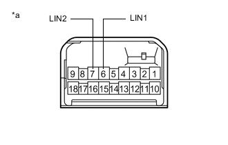
*a Component without harness connected
(Power Window Regulator Master Switch Assembly)
Remove the power window regulator master switch assembly.
-
Measure the resistance according to the value(s) in the table below.
Standard Resistance Tester Connection Condition Specified Condition 7 (LIN2) - 6 (LIN1) Always Below 1 Ω Result Proceed to OK NG
NG
REPLACE POWER WINDOW REGULATOR MASTER SWITCH ASSEMBLY Click here
OK
-
-
CHECK HARNESS AND CONNECTOR (POWER WINDOW REGULATOR MASTER SWITCH ASSEMBLY - POWER WINDOW REGULATOR MOTOR ASSEMBLY (for Driver Door))
-
Disconnect the H4 power window regulator motor assembly (for driver door) connector.
-
Measure the resistance according to the value(s) in the table below.
Note
Make sure that each ECU is in sleep mode before performing the inspection. To enter sleep mode, turn the ignition switch from ON to off and wait for 180 seconds or more without operating any switches.
Standard Resistance Tester Connection Condition Specified Condition H6-7 (LIN2) - H4-9 (LIN) Ignition switch off Below 1 Ω H6-7 (LIN2) or H4-9 (LIN) - Body ground Ignition switch off 10 kΩ or higher Result Proceed to OK NG
NG
REPAIR OR REPLACE HARNESS OR CONNECTOR
OK
-
-
INSPECT INSTRUMENT PANEL JUNCTION BLOCK ASSEMBLY
-
Remove the instrument panel junction block assembly.
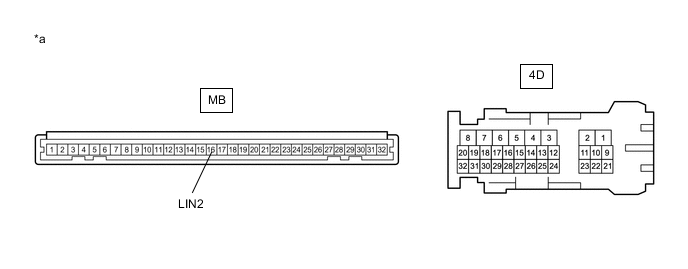
*a Component without harness connected
(Instrument Panel Junction Block Assembly)
- - -
Remove the main body ECU (multiplex network body ECU) from the instrument panel junction block assembly.
-
Measure the resistance according to the value(s) in the table below.
Tech Tips
This inspection is to check the LIN communication line in the instrument panel junction block assembly that connects the wire harness to the built-in main body ECU (multiplex network body ECU).
Standard Resistance Tester Connection Condition Specified Condition 4D-25 - MB-16 (LIN2) Always Below 1 Ω Result Proceed to OK NG
NG
REPLACE INSTRUMENT PANEL JUNCTION BLOCK ASSEMBLY Click here
OK
-
-
CHECK HARNESS AND CONNECTOR (INSTRUMENT PANEL JUNCTION BLOCK ASSEMBLY - EACH ECU)
-
Disconnect the I5 power window regulator motor assembly (for front passenger door) connector.
-
Disconnect the H6 power window regulator master switch assembly connector.
-
Disconnect the S5 sliding roof ECU (sliding roof drive gear sub-assembly) connector.*
-
*: w/ Sliding Roof System
-
-
Measure the resistance according to the value(s) in the table below.
Note
Make sure that each ECU is in sleep mode before performing the inspection. To enter sleep mode, turn the ignition switch from ON to off and wait for 180 seconds or more without operating any switches.
Standard Resistance Tester Connection Condition Specified Condition 4D-25 - H6-6 (LIN1) Ignition switch off Below 1 Ω 4D-25 - S5-11 (MPX1)* Ignition switch off Below 1 Ω 4D-25 - I5-9 (LIN) Ignition switch off Below 1 Ω H6-6 (LIN1) - Body ground Ignition switch off 10 kΩ or higher S5-11 (MPX1) - Body ground* Ignition switch off 10 kΩ or higher 4D-25 - Body ground Ignition switch off 10 kΩ or higher I5-9 (LIN) - Body ground Ignition switch off 10 kΩ or higher
-
*: w/ Sliding Roof System
Result Proceed to OK NG -
NG
REPAIR OR REPLACE HARNESS OR CONNECTOR
OK
-
-
CHECK POWER WINDOW REGULATOR MASTER SWITCH ASSEMBLY
-
Reconnect the 4D instrument panel junction block assembly connector.
-
Reconnect the H4 power window regulator motor assembly (for driver door) connector.
-
Reconnect the I5 power window regulator motor assembly (for front passenger door) connector.
-
Reconnect the S5 sliding roof ECU (sliding roof drive gear sub-assembly) connector.*
-
*: w/ Sliding Roof System
-
-
Clear the DTCs.
Body Electrical > Main Body > Clear DTCs -
After 10 seconds have elapsed, check if the same DTC is output again.
Body Electrical > Main Body > Trouble CodesResult Result Proceed to DTC B2325 is output A DTC B2325 is not output B
B
REPLACE POWER WINDOW REGULATOR MASTER SWITCH ASSEMBLY Click here
A
-
-
CHECK POWER WINDOW REGULATOR MOTOR ASSEMBLY (for Driver Door)
-
Reconnect the H6 power window regulator master switch assembly connector.
-
Disconnect the H4 power window regulator motor assembly (for driver door) connector.
-
Clear the DTCs.
Body Electrical > Main Body > Clear DTCs -
After 10 seconds have elapsed, check if the same DTC is output again.
Body Electrical > Main Body > Trouble CodesResult Result Proceed to DTC B2325 is output A DTC B2325 is not output B
B
REPLACE POWER WINDOW REGULATOR MOTOR ASSEMBLY (for Driver Door) Click here
A
-
-
CHECK POWER WINDOW REGULATOR MOTOR ASSEMBLY (for Front Passenger Door)
-
Reconnect the H4 power window regulator motor assembly (for driver door) connector.
-
Disconnect the I5 power window regulator motor assembly (for front passenger door) connector.
-
Clear the DTCs.
Body Electrical > Main Body > Clear DTCs -
After 10 seconds have elapsed, check if the same DTC is output again.
Body Electrical > Main Body > Trouble CodesResult Result Proceed to DTC B2325 is output (w/ Sliding Roof System) A DTC B2325 is output (w/o Sliding Roof System) B DTC B2325 is not output C
B
REPLACE MAIN BODY ECU (MULTIPLEX NETWORK BODY ECU) Click here
C
REPLACE POWER WINDOW REGULATOR MOTOR ASSEMBLY (for Front Passenger Door) Click here
A
-
-
CHECK SLIDING ROOF ECU (SLIDING ROOF DRIVE GEAR SUB-ASSEMBLY)
-
Reconnect the I5 power window regulator motor assembly (for front passenger door) connector.
-
Disconnect the S5 sliding roof ECU (sliding roof drive gear sub-assembly) connector.
-
Clear the DTCs.
Body Electrical > Main Body > Clear DTCs -
After 10 seconds have elapsed, check if the same DTC is output again.
Body Electrical > Main Body > Trouble CodesResult Result Proceed to DTC B2325 is output A DTC B2325 is not output B
A
REPLACE MAIN BODY ECU (MULTIPLEX NETWORK BODY ECU) Click here
B
REPLACE SLIDING ROOF ECU (SLIDING ROOF DRIVE GEAR SUB-ASSEMBLY) Click here
-