MAIN BODY ECU REMOVAL
PROCEDURE
-
PRECAUTION
Note
-
After turning the ignition switch off, waiting time may be required before disconnecting the cable from the negative (-) battery terminal. Therefore, make sure to read the disconnecting the cable from the negative (-) battery terminal notices before proceeding with work.
-
To prevent damage to the main body ECU (multiplex network body ECU), disconnect the cable from the negative (-) battery terminal and discharge the door control battery before replacing or removing/installing the main body ECU (multiplex network body ECU).
for LHD
-
-
DISCONNECT CABLE FROM NEGATIVE BATTERY TERMINAL
Note
When disconnecting the cable, some systems need to be initialized after the cable is reconnected.
-
Discharge the door control battery. (for LHD)
Tech Tips
The door control battery will discharge completely within approximately 30 minutes after the ignition switch is turned off.
The time required to discharge the door control battery is reduced when it is not fully charged.
-
Connect the GTS to the DLC3.
-
Turn the GTS on.
-
Enter the following menus: Body Electrical / Main Body / Active Test.
-
Disconnect the cable from the negative (-) battery terminal.
-
Perform the Active Test according to the display on the GTS.
Body Electrical > Main Body > Active TestTester Display Measurement Item Control Range Diagnostic Note Shock Detection Unlock Operate door lock motor UNLOCK/LOCK -
Body Electrical > Main Body > Active TestTester Display Shock Detection Unlock Tech Tips
Perform the Active Test until the door lock/unlock operation can no longer be performed and "Lost communication with vehicle" is displayed on the GTS.
-
-
-
REMOVE FRONT DOOR SCUFF PLATE LH
-
REMOVE COWL SIDE TRIM SUB-ASSEMBLY LH
-
DISCONNECT FRONT DOOR OPENING TRIM WEATHERSTRIP LH
-
REMOVE INSTRUMENT PANEL FINISH PANEL END LH
-
REMOVE NO. 1 INSTRUMENT PANEL UNDER COVER SUB-ASSEMBLY (for LHD)
-
DISCONNECT HOOD LOCK CONTROL LEVER SUB-ASSEMBLY (for LHD)
-
REMOVE LOWER INSTRUMENT PANEL FINISH PANEL SUB-ASSEMBLY (for LHD)
-
REMOVE NO. 2 INSTRUMENT PANEL UNDER COVER SUB-ASSEMBLY (for RHD)
-
REMOVE LOWER INSTRUMENT PANEL SUB-ASSEMBLY (for RHD)
-
REMOVE INSTRUMENT PANEL JUNCTION BLOCK ASSEMBLY WITH MAIN BODY ECU (for LHD)
-
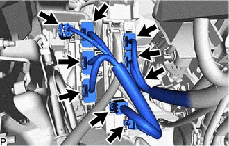
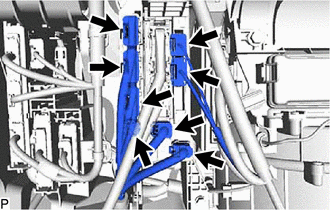
Disconnect each connector.
-
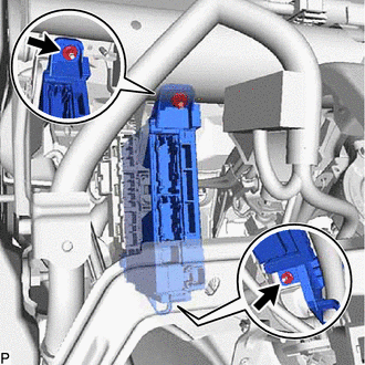
Disengage the claw and pull down the lock lever to disconnect the connector as shown in the illustration.
-
Disengage the claw and pull down the lock lever to disconnect the connector as shown in the illustration.
-
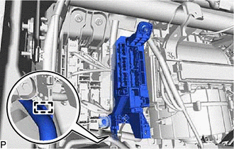
Disengage the clamp.
-
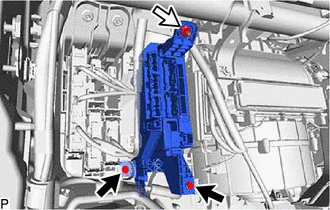
Remove the 2 nuts.
-
Disengage the clamp as shown in the illustration.
-
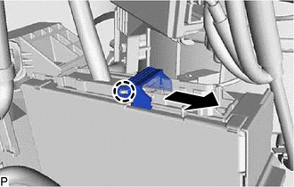
Pull out the instrument panel junction block assembly with main body ECU.
-
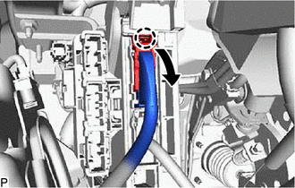
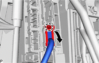
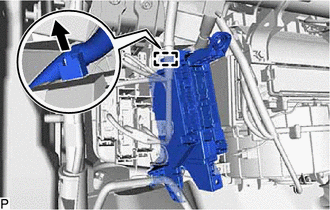
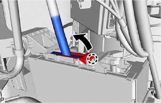
Disengage the claw and raise the lock lever to disconnect the connector as shown in the illustration.
-
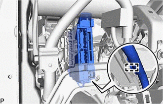
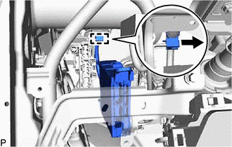
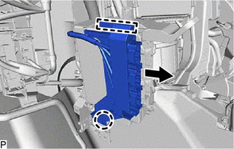
Disengage the claw and slide the connector lock as shown in the illustration.
-
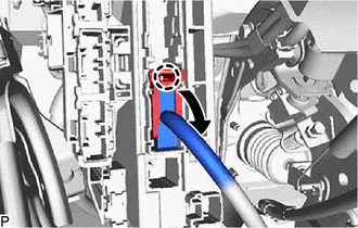
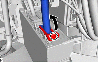
Disengage the claw and raise the lock lever to disconnect the connector as shown in the illustration and remove the instrument panel junction block assembly with main body ECU.
-
-
REMOVE INSTRUMENT PANEL JUNCTION BLOCK ASSEMBLY WITH MAIN BODY ECU (for RHD)
-
Disconnect each connector.
-

Disengage the claw and pull down the lock lever to disconnect the connector as shown in the illustration.
-
Disengage the claw and pull down the lock lever to disconnect the connector as shown in the illustration.
-
Disengage the clamp.
-

Bolt 
Nut Remove the 2 bolts and nut.
-
Disengage the clamp as shown in the illustration.
-
Disengage the claw and guide to disconnect the connector holder as shown in the illustration.
-
Pull out the instrument panel junction block assembly with main body ECU.
-
Disengage the claw and raise the lock lever to disconnect the connector as shown in the illustration.
-
Disengage the claw and slide the connector lock as shown in the illustration.
-
Disengage the claw and raise the lock lever to disconnect the connector as shown in the illustration and remove the instrument panel junction block assembly with main body ECU.
-
-
REMOVE MAIN BODY ECU (MULTIPLEX NETWORK BODY ECU)
-
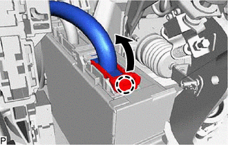
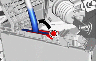
Press the claw of the instrument panel junction block assembly as shown in the illustration to release the lock.
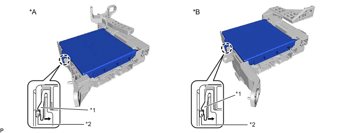
*A for LHD *B for RHD *1 Instrument Panel Junction Block Assembly *2 Main Body ECU (Multiplex Network Body ECU) -
With the instrument panel junction block assembly lock released, insert a screwdriver with its tip wrapped with protective tape horizontally between the main body ECU (multiplex network body ECU) and instrument panel junction block assembly.
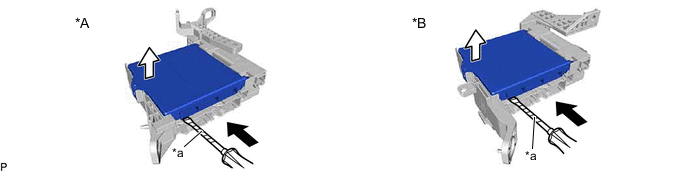
*A for LHD *B for RHD *a Protective Tape - - Note
-
Use a screwdriver with a diameter between 5.0 mm (0.197 in.) and 6.3 mm (0.248 in.) and a length of approximately 90 mm (3.54 in.).
-
Do not insert the screwdriver under the connector socket of the main body ECU (multiplex network body ECU).
-
-
Using the screwdriver, carefully raise the main body ECU (multiplex network body ECU) to the position where the connector becomes disconnected.
Note
Do not twist the screwdriver to raise the main body ECU (multiplex network body ECU).
-
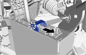
Raise the main body ECU (multiplex network body ECU) as shown by the arrow (1), and then pull it out as shown by the arrow (2) in the illustration.
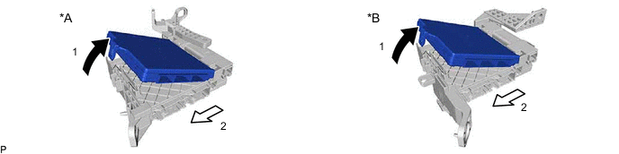
*A for LHD *B for RHD Note
Do not touch the main body ECU (multiplex network body ECU) connector.
-