INTEGRATION RELAY REMOVAL
PROCEDURE
-
PRECAUTION
Note
After turning the ignition switch off, waiting time may be required before disconnecting the cable from the negative (-) battery terminal. Therefore, make sure to read the disconnecting the cable from the negative (-) battery terminal notices before proceeding with work.
-
DISCONNECT CABLE FROM NEGATIVE BATTERY TERMINAL
Note
When disconnecting the cable, some systems need to be initialized after the cable is reconnected.
-
DISCONNECT BRAKE MASTER CYLINDER RESERVOIR ASSEMBLY (for LHD)
-
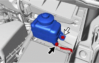
Disconnect the connector.
-
Remove the bolt.
-
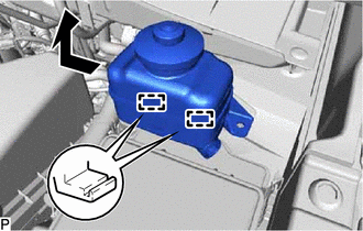
Disengage the 2 guides and disconnect the brake master cylinder reservoir assembly as shown in the illustration.
-
-
REMOVE RESERVOIR BRACKET (for LHD)
-
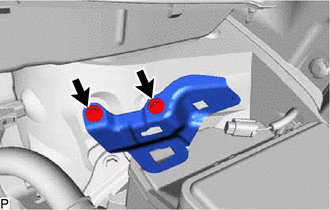
Remove the 2 bolts and reservoir bracket.
-
-
REMOVE NO. 1 RELAY BLOCK COVER
-
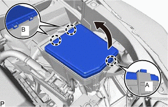
Disengage the claw (A) as shown in the illustration.
-
Disengage the 2 claws (B) and remove the No. 1 relay block cover.
-
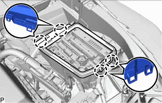
Disengage the 4 claws and remove the No. 1 relay block cover.
-
-
REMOVE SEMICONDUCTOR PWR INTEGRATION ECU
-
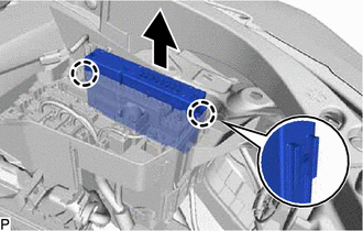
Disengage the 2 claws.
-
Pull up the semiconductor pwr integration ECU as shown in the illustration.
Note
When pulling the semiconductor pwr integration ECU, take care not to damage it.
-
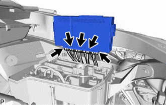
Disconnect the 5 connectors and remove the semiconductor pwr integration ECU.
Note
When pulling the semiconductor pwr integration ECU, take care not to damage it.
-