PANORAMIC VIEW MONITOR SYSTEM, Diagnostic DTC:C1621
| DTC Code | DTC Name |
|---|---|
| C1621 | Back Camera Power Supply Failure |
DESCRIPTION
DTC C1621 is stored if the parking assist ECU determines that the input/output signal communication with the television camera assembly is abnormal.
| DTC No. | Detection Item | DTC Detection Condition | Trouble Area |
|---|---|---|---|
| C1621 | Back Camera Power Supply Failure | Television camera assembly power supply malfunction |
|
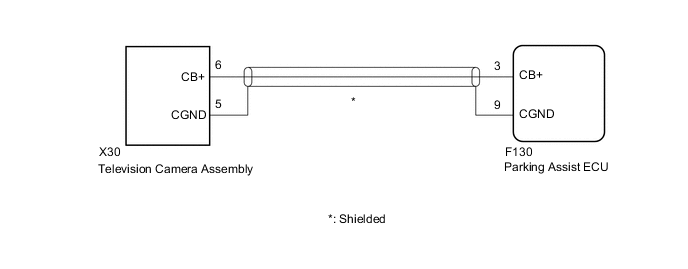
WIRING DIAGRAM
CAUTION / NOTICE / HINT
Note
-
When "!" mark is displayed on the multi-display after the cable is disconnected from the negative (-) battery terminal, correct the steering angle neutral point.
-
Depending on the parts that are replaced or operations that are performed during vehicle inspection or maintenance, calibration of other systems as well as the panoramic view monitor system may be needed.
PROCEDURE
-
CHECK HARNESS AND CONNECTOR (PARKING ASSIST ECU - TELEVISION CAMERA ASSEMBLY)
-
Disconnect the F130 parking assist ECU connector.
-
Disconnect the X30 television camera assembly connector.
-
Measure the resistance according to the value(s) in the table below.
Standard Resistance Tester Connection Condition Specified Condition F130-3 (CB+) - X30-6 (CB+) Always Below 1 Ω F130-9 (CGND) - X30-5 (CGND) Always Below 1 Ω F130-3 (CB+) or X30-6 (CB+) - Body ground Always 10 kΩ or higher F130-9 (CGND) or X30-5 (CGND) - Body ground Always 10 kΩ or higher Result Proceed to OK NG
NG 
REPAIR OR REPLACE HARNESS OR CONNECTOR
OK 
-
-
CHECK PARKING ASSIST ECU (CB+, CGND)
-
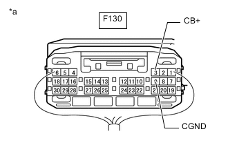
*a Component with harness connected
(Parking Assist ECU)
Remove the parking assist ECU with the connector still connected.
-
Measure the resistance according to the value(s) in the table below.
Standard Resistance Tester Connection Condition Specified Condition F130-9 (CGND) - Body ground Always Below 1 Ω -
Measure the voltage according to the value(s) in the table below.
Standard Voltage Tester Connection Switch Condition Specified Condition F130-3 (CB+) - F130-9 (CGND) Ignition switch ACC 5.5 to 7.05 V Result Proceed to OK NG
OK
REPLACE TELEVISION CAMERA ASSEMBLY Click here
NG
REPLACE PARKING ASSIST ECU Click here
-