PANORAMIC VIEW MONITOR SYSTEM DIAGNOSIS SYSTEM
-
PARKING ASSIST MONITOR DIAGNOSIS SYSTEM
-
For panoramic view monitor system diagnosis, signals received by the parking assist ECU can be checked, and the panoramic view monitor system can be calibrated, adjusted and checked using the navigation receiver assembly*1 or radio and display receiver assembly*2.
*1: for Navigation Receiver Type
*2: for Radio and Display Type
Note
Depending on the parts that are replaced or operations that are performed during vehicle inspection or maintenance, calibration of other systems as well as the panoramic view monitor system may be needed.
Tech Tips
The displayed screens and items may differ depending on vehicle specifications.
-
-
DIAGNOSIS SCREEN TRANSITION (VIEW ADJUSTMENT)
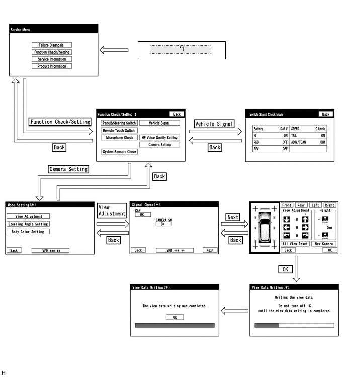
*1 Start diagnostic mode -
DIAGNOSIS SCREEN TRANSITION (STEERING ANGLE SETTING)
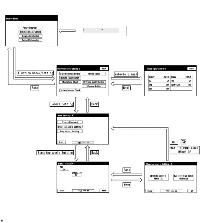
*1 Start diagnostic mode *2 or -
DIAGNOSIS SCREEN TRANSITION (BODY COLOR SETTING)
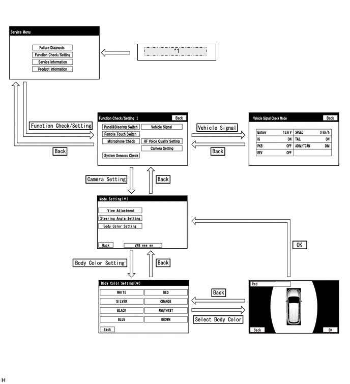
*1 Start diagnostic mode -
DIAGNOSTIC MODE
-
Diagnostic mode
for Navigation Receiver Type: Click here
for Radio and Display Type: Click here
-
Failure diagnosis
for Navigation Receiver Type: Click here
for Radio and Display Type: Click here
-
System check (check using system check mode screen)
for Navigation Receiver Type: Click here
for Radio and Display Type: Click here
-
Finish diagnostic mode.
for Navigation Receiver Type: Click here
for Radio and Display Type: Click here
-
-
SIGNAL CHECK (parking assist ECU input signal)
-
Start diagnostic mode.
for Navigation Receiver Type: Click here
for Radio and Display Type: Click here
-
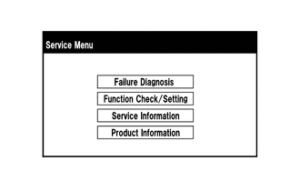
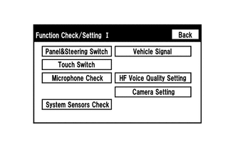
Select "Function Check/Setting" on the "Service Menu" screen to display the "Function Check/Setting I" screen.
-
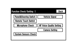
Select "Camera Setting" on the "Function Check/Setting I" screen.
Tech Tips
After "Camera Setting" is selected, the screen transitions differ depending on whether initialization of the parking assist ECU was performed after parking assist ECU replacement.
Parking Assist ECU Initialization Screen Transition Not performed "Signal Check" screen Performed "Mode Setting" screen -
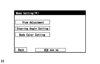
When the screen changes to the "Mode Setting" screen, select "View Adjustment" to display the "Signal Check" screen.
Tech Tips
To select a grayed out item, select and hold the item for 2 seconds or more.
-
-
Signal check
-
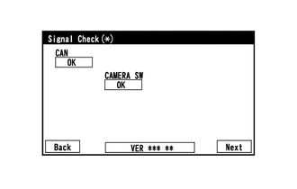
On the "Signal Check" screen, it is possible to inspect the state of signals sent to the parking assist ECU and check the settings.
Item Inspection Detail Note CAN Speed signal input When "CHK" (red) is displayed, selecting "Next" will not change to the next screen. CAMERA SW Panoramic view monitor switch signal input Tech Tips
-
When "CHK" (red) is displayed, perform inspections based on the result of the following inspections.
-
If performing the adjustment after proceeding to the next screen, confirm that all items display "OK" (blue) before selecting "Next".
-
-
-
CAN inspection
Tech Tips
If "CHK" (red) is displayed for "CAN", check for DTCs and perform troubleshooting based on the output DTCs.
-
CAMERA SW inspection
-
Check that "OK" (blue) is displayed for "CAMERA SW" and select "OK".
Tech Tips
If "CHK" (red) remains displayed or the "CAMERA SW" inspection result is not normal, perform troubleshooting according to the Problem Symptoms Table ("CHK" message(s) are displayed on the "Signal Check" screen).
-
-
Finish diagnostic mode.
for Navigation Receiver Type: Click here
for Radio and Display Type: Click here
-
-
Body Color Setting
Tech Tips
-
This function is used for only customers who request it.
-
The color of the vehicle icon displayed on the moving view screen or the panoramic view screen can be changed from the diagnosis screen.
-
Start diagnostic mode.
for Navigation Receiver Type: Click here
for Radio and Display Type: Click here
-
Select "Function Check/Setting" on the "Service Menu" screen.
-
Select "Camera Setting" on the "Function Check/Setting I" screen.
-
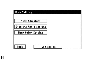
Select "Body Color Setting" on the "Mode Setting" screen to display the "Body Color Setting" screen.
Tech Tips
To select a grayed out item, select and hold the item for 2 seconds or more.
-
-
Body color setting
-
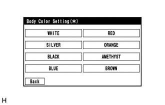
Select the color to change, and display the result confirm screen.
Tech Tips
"White" is initialized.
-
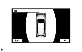
Select "OK" on the result confirm screen, and display the mode setting screen.
Note
Changing the color of the icon may make the icon border hard to see on the moving view screen or panoramic view screen.
Tech Tips
-
The body color setting screen does not display the actual body color.
-
To change the body color setting again, select "Back" and select it again.
-
The setting is memorized when the mode setting screen is displayed.
-
-
-
Finish diagnostic mode.
for Navigation Receiver Type: Click here
for Radio and Display Type: Click here
-
-
CALIBRATION WHEN SERVICING VEHICLE
Note
Depending on the parts that are replaced or operations that are performed during vehicle inspection or maintenance, calibration of other systems as well as the panoramic view monitor system may be needed.