BLIND SPOT MONITOR SYSTEM OPERATION CHECK
-
BLIND SPOT MONITOR BEAM AXIS INSPECTION
-
Procedure to enter Test Mode
-
Connect the GTS to the DLC3.
-
Turn the engine switch on (IG).
-
Turn the blind spot monitor main switch (warning canceling switch assembly) on.
-
Turn the GTS on.
-
Switch the blind spot monitor sensor to Test Mode using the GTS.
Enter the following menus: Body Electrical / Blind Spot Monitor Master or Blind Spot Monitor Slave / Utility / BSM Master Beam Axis Inspection or BSM Slave Beam Axis Inspection.
Body Electrical > Blind Spot Monitor Master > UtilityTester Display BSM Master Beam Axis Inspection
Body Electrical > Blind Spot Monitor Slave > UtilityTester Display BSM Slave Beam Axis Inspection -
Finish Test Mode.
-
-
-
BLIND SPOT MONITOR BEAM AXIS CONFIRMATION
-
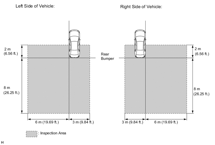
When performing the blind spot monitor beam axis confirmation, move the vehicle to a place where the space shown in the illustration can be secured.
Note
-
Perform this inspection on level ground.
-
Make sure that there are no metal objects around the vehicle or on the ground.
-
Unload the vehicle before beginning the inspection.
-
Confirm that the tire pressure is correct before beginning the inspection.
-
Do not place an object other than the reflector (such as a large metallic object) in or allow people to enter the inspection area (W 9 m (29.53 ft.) x L 10 m (32.81 ft.) x H 4 m (13.12 ft.)) shown in the illustration.
-
Check that DTC C1ABB and DTC C1ABC are not output.
-
-
Place the reflector.
-
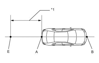
Hang a string (with weight) from the center of the vehicle's rear emblem. Mark the vehicle's rear center point on the ground. Repeat for the front of the vehicle. (Mark (A) and (B))
-
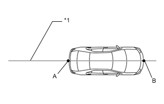
*1 Vehicle center line Draw a vehicle center line so that it passes through mark (A) and (B) (front and rear center points).
-
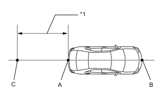
*1 382 mm (1.25 ft.) Mark the position on the center line 382 mm (1.25 ft.) behind the rear bumper. (Mark (C))
-
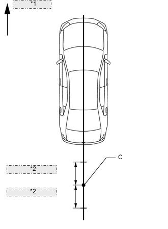
*1 Vehicle front *2 300 mm (11.8 in.) Prepare 2 pieces of string of 600 mm (1.97 ft.) in length and secure the end of each string at a point 300 mm (11.8 in.) from mark (C) as shown in the illustration.
-
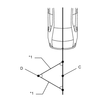
Vehicle rear *1 String Pull the end of each string and mark the position where each string meets on the left side. (Mark (D))
-
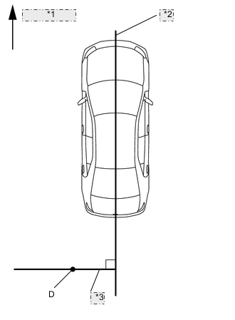
*1 Vehicle front *2 Vehicle center line *3 Line P Draw a line (P) so that it passes through mark (D) and is perpendicular to the vehicle center line.
-
*1 429 mm (1.41 ft.) Mark the position on the center line 429 mm (1.41 ft.) behind the rear bumper. (Mark (E))
-
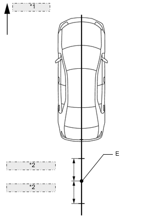
*1 Vehicle front *2 300 mm (11.8 in.) Prepare 2 pieces of string of 600 mm (1.97 ft.) in length and secure the end of each string at a point 300 mm (11.8 in.) from mark (E) as shown in the illustration.
-
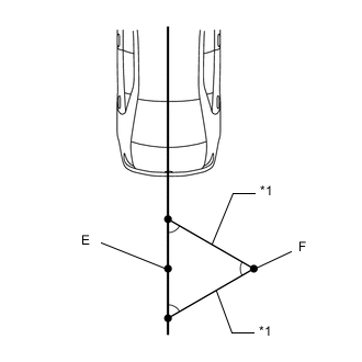
Vehicle rear *1 String Pull the end of each string and mark the position where each string meets on the right side. (Mark (F))
-
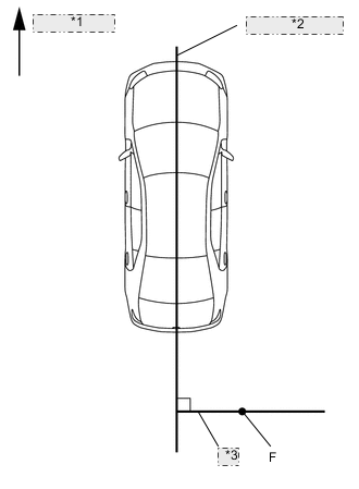
*1 Vehicle front *2 Vehicle center line *3 Line Q Draw a line (Q) so that it passes through mark (F) and is perpendicular to the vehicle center line.
-
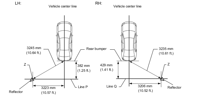
Set the reflector at the position (Z) shown in the illustration below.
- SST
- 09870-60000 ( 09870-60010 )
- 09870-60040
Note
-
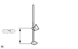
*1 592 mm (1.94 ft.) Set the reflector so that its center is 592 mm (1.94 ft.) above the ground.
-
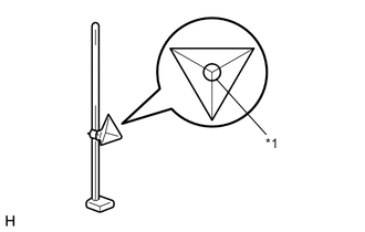
*1 Center of triangular pyramid The center of triangular pyramid is the reference point for the setting position and angle.
-
-
Perform the blind spot monitor beam axis display.
-
Connect the GTS to the DLC3.
-
Turn the engine switch on (IG).
-
Turn the blind spot monitor main switch (warning canceling switch assembly) on.
-
Turn the GTS on.
-
Enter the following menus: Body Electrical / Blind Spot Monitor Master or Blind Spot Monitor Slave / Utility / BSM Master Beam Axis Display or BSM Slave Beam Axis Display.
Body Electrical > Blind Spot Monitor Master > UtilityTester Display BSM Master Beam Axis Display
Body Electrical > Blind Spot Monitor Slave > UtilityTester Display BSM Slave Beam Axis Display -
Check the results displayed for the BSM beam axis display.
Tech Tips
If the results are outside the allowable range, try again as the reflector setting position may be incorrect or a metal object may exist near the detection area.
-
-
Perform the blind spot monitor beam axis adjustment.
-
Enter the following menus: Body Electrical / Blind Spot Monitor Master or Blind Spot Monitor Slave / Utility / BSM Master Beam Axis Adjustment or BSM Slave Beam Axis Adjustment.
Tech Tips
When values on the axis display are in the allowable range, performing this adjustment compensates the values to the normal value.
Body Electrical > Blind Spot Monitor Master > UtilityTester Display BSM Master Beam Axis Adjustment
Body Electrical > Blind Spot Monitor Slave > UtilityTester Display BSM Slave Beam Axis Adjustment
-
-
-
BLIND SPOT MONITOR SENSOR INSTALLATION CONDITION INSPECTION
Note
-
Perform this inspection on level ground.
-
Unload the vehicle before beginning the inspection.
-
Confirm that the tire pressure is correct before beginning the inspection.
-
Remove the rear bumper.
-
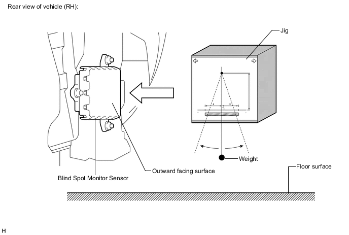
Attach a jig similar to the one shown in the illustration to the outward facing surface of the blind spot monitor sensor and check that the blind spot monitor sensor is perpendicular to the floor surface or within the allowable range.
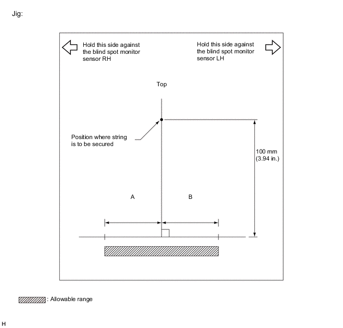
Standard A B Blind spot monitor sensor LH (Master) 8 mm
(0.315 in.)
-8 mm
(-0.315 in.)
Blind spot monitor sensor RH (Slave) 8 mm
(0.315 in.)
-8 mm
(-0.315 in.)
-
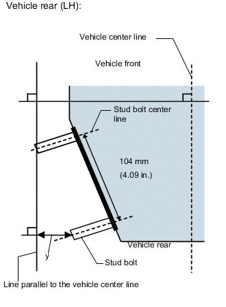
Using the sensor installation stud bolt center lines as a reference, check that the stud bolts are as shown in the illustration.
-