RADIO ANTENNA CORD INSTALLATION
PROCEDURE
-
INSTALL NO. 2 ANTENNA CORD SUB-ASSEMBLY (for Normal Roof)
Tech Tips
Butyl tape and adhesive tape are not available as supply parts. If these pieces of tape still have enough adhesion to secure the No. 2 antenna cord sub-assembly to the roof headlining assembly, reuse them. If the adhesive tape and/or the butyl tape is no longer sticky, apply new tape following the procedure below.
-
Apply new butyl tape.
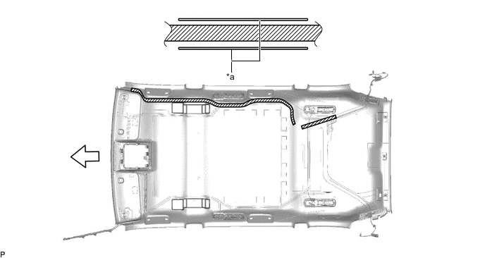
*a Marking - - 
Butyl tape 
Front
-
Remove the old butyl tape from the roof headlining assembly.
-
Prepare the appropriate amount of new butyl tape.
Tech Tips
Be careful not to touch the adhesive surface.
-
Apply the butyl tape to the roof headlining assembly while aligning the tape with the markings on the roof headlining assembly.
-
Peel off the release paper from the butyl tape.
-
-
Install the No. 2 antenna cord sub-assembly to the roof headlining assembly from the front of the roof headlining assembly.
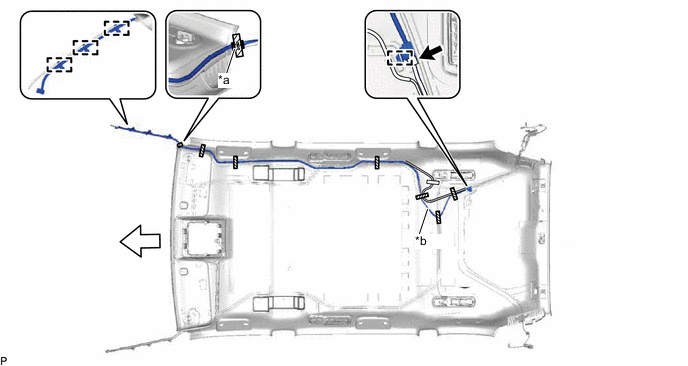
*a Protrusion *b Adjustment Area Adhesive Tape 
Marking Tape Front - - -
Engage each clamp.
-
Connect the connector.
-
Put the pieces of adhesive tape back to the positions shown in the illustration in order to secure the No. 2 antenna cord sub-assembly and washer hose to the roof headlining assembly.
Tech Tips
-
If the tape is no longer sticky, use other tape, such as packing tape, that has enough adhesion to secure the antenna cord to the roof headlining assembly.
-
Align the marking tape on the No. 2 antenna cord sub-assembly with the protrusion of the roof headlining assembly, and wrap tape around the antenna cord and roof headlining assembly once or twice to securely hold them.
-
Align the marking tape on the washer hose with the clamp of the No. 2 antenna cord sub-assembly.
-
Secure the extra length of the No. 2 antenna cord sub-assembly in the adjustment area shown in the illustration.
-
-
-
INSTALL NO. 2 ANTENNA CORD SUB-ASSEMBLY (for Sliding Roof)
Tech Tips
Butyl tape and adhesive tape are not available as supply parts. If these pieces of tape still have enough adhesion to secure the No. 2 antenna cord sub-assembly to the roof headlining assembly, reuse them. If the adhesive tape and/or the butyl tape is no longer sticky, apply new tape following the procedure below.
-
Apply new butyl tape.
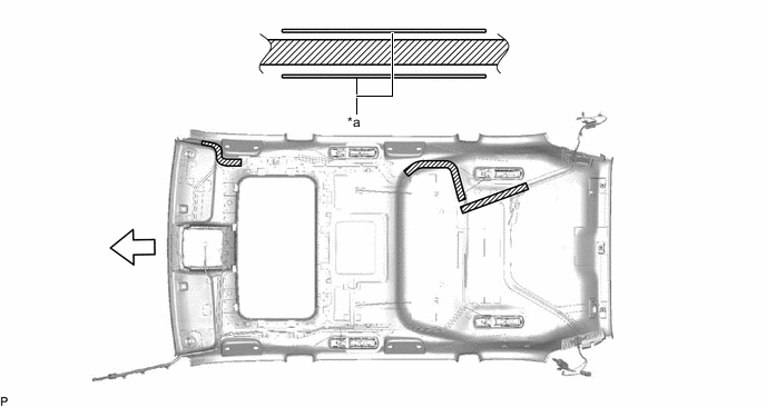
*a Marking - - Butyl tape Front
-
Remove the old butyl tape from the roof headlining assembly.
-
Prepare the appropriate amount of new butyl tape.
Tech Tips
Be careful not to touch the adhesive surface.
-
Apply the butyl tape to the roof headlining assembly while aligning the tape with the markings on the roof headlining assembly.
-
Peel off the release paper from the butyl tape.
-
-
Install the No. 2 antenna cord sub-assembly to the roof headlining assembly from the front of the roof headlining assembly.
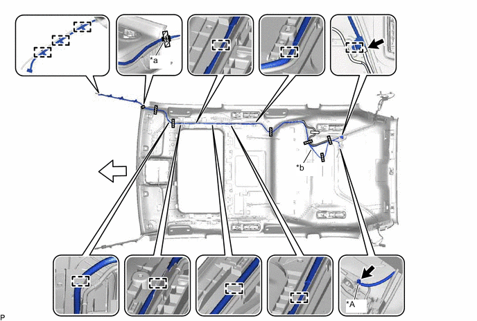
*A w/ DAB Function - - *a Protrusion *b Adjustment Area Adhesive Tape Marking Tape Front - - -
Engage each clamp.
-
Connect each connector.
-
Put the pieces of adhesive tape back to the positions shown in the illustration in order to secure the No. 2 antenna cord sub-assembly and washer hose to the roof headlining assembly.
Tech Tips
-
If the tape is no longer sticky, use other tape, such as packing tape, that has enough adhesion to secure the antenna cord to the roof headlining assembly.
-
Align the marking tape on the No. 2 antenna cord sub-assembly with the protrusion of the roof headlining assembly, and wrap tape around the antenna cord and roof headlining assembly once or twice to securely hold them.
-
Align the marking tape on the washer hose with the clamp of the No. 2 antenna cord sub-assembly.
-
Secure the extra length of the No. 2 antenna cord sub-assembly in the adjustment area shown in the illustration.
-
-
-
INSTALL ROOF HEADLINING ASSEMBLY
-
INSTALL ANTENNA CORD SUB-ASSEMBLY
-
Engage the 4 clamps to install the antenna cord sub-assembly.
-
-
INSTALL NO. 4 HEATER TO REGISTER DUCT (for LHD)
-
INSTALL NO. 1 HEATER TO REGISTER DUCT (for RHD)
-
INSTALL INSTRUMENT PANEL SAFETY PAD SUB-ASSEMBLY