STEERING COLUMN ASSEMBLY INSTALLATION
PROCEDURE
-
ALIGN FRONT WHEELS FACING STRAIGHT AHEAD
-
INSTALL STEERING POST ASSEMBLY
-
Install the steering post assembly with the bolt and 2 nuts.
- Torque:
- 25 N*m { 255 kgf*cm, 18 ft.*lbf }
Note
Make sure that the wire harness is not interfering with the steering post assembly.
-
Connect the 2 connectors.
-
Engage the 2 clamps.
-
Install the ground wire with the bolt.
- Torque:
- 8.35 N*m { 85 kgf*cm, 74 in.*lbf }
-
Connect each connector and engage each wire harness clamp to the steering post assembly.
-
-
INSTALL BRAKE PEDAL SUPPORT ASSEMBLY
for LHD: Click here
for RHD: Click here
-
INSTALL NO. 4 AIR DUCT SUB-ASSEMBLY (for LHD)
-
Engage the 2 claws and guide to install the No. 4 air duct sub-assembly.
-
Install the bolt.
- Torque:
- 9.8 N*m { 100 kgf*cm, 87 in.*lbf }
-
-
INSTALL NO. 3 AIR DUCT SUB-ASSEMBLY (for RHD)
-
Engage the 2 claws and guide to install the No. 3 air duct sub-assembly.
-
-
CONNECT STEERING INTERMEDIATE SHAFT ASSEMBLY
-
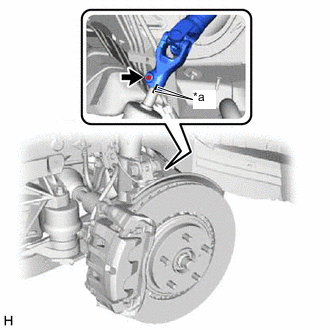
*a Matchmark Align the matchmarks on the steering intermediate shaft assembly and steering link assembly.
-
Connect the steering intermediate shaft assembly to the steering link assembly.
-
Install a new bolt.
- Torque:
- 35.3 N*m { 360 kgf*cm, 26 ft.*lbf }
-
Install the steering intermediate shaft assembly to the steering column hole shield.
-
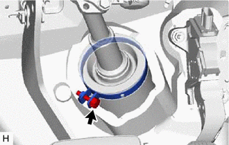
Tighten the bolt.
-
-
INSTALL LOWER NO. 1 INSTRUMENT PANEL AIRBAG ASSEMBLY
-
INSTALL TURN SIGNAL SWITCH ASSEMBLY WITH SPIRAL CABLE SUB-ASSEMBLY
Note
-
Do not replace the spiral cable with sensor sub-assembly with the battery connected and the ignition switch ON.
-
Do not rotate the spiral cable with sensor sub-assembly without the steering wheel assembly with the battery connected and the ignition switch ON.
-
Ensure that the steering wheel assembly is installed and aligned straight when inspecting the steering sensor.
-
Engage the 3 claws to install the turn signal switch assembly with spiral cable sub-assembly to the steering column assembly.
-
Connect each connector to the turn signal switch assembly with spiral cable sub-assembly.
-
-
INSTALL UPPER STEERING COLUMN COVER
-
Engage the 2 claws to install the upper steering column cover.
-
Engage the 6 clips to the upper steering column cover.
-
-
INSTALL LOWER STEERING COLUMN COVER
-
Engage the 3 claws to install the lower steering column cover.
-
Install the 2 screws.
-
-
ALIGN FRONT WHEELS FACING STRAIGHT AHEAD
-
INSPECT AND ADJUST SPIRAL CABLE WITH SENSOR SUB-ASSEMBLY
-
INSTALL STEERING WHEEL ASSEMBLY
-
CHECK STEERING WHEEL CENTER POINT
-
INSTALL HORN BUTTON ASSEMBLY
-
INSTALL FRONT WHEEL
- Torque:
- 103 N*m { 1050 kgf*cm, 76 ft.*lbf }
-
ADJUST PARKING ASSIST MONITOR SYSTEM (w/ Parking Assist Monitor System)