STEERING COLUMN ASSEMBLY DISASSEMBLY
CAUTION / NOTICE / HINT
Note
-
Do not drop the power steering ECU assembly and power steering motor assembly, strike it with tools or subject it to impacts.
-
If the power steering ECU assembly and power steering motor assembly is subjected to an impact, replace it with a new one.
-
Do not pull the wire harness of the electric power steering column sub-assembly.
-
Do not allow any moisture to come into contact with the power steering ECU assembly and power steering motor assembly.
-
Do not loosen any bolts not mentioned in the procedure.
PROCEDURE
-
REMOVE STEERING LOCK ACTUATOR ASSEMBLY (w/ Smart Entry and Start System)
-
Secure the steering column assembly in a vise between aluminum plates.
Note
Do not overtighten the vise, as the steering column assembly may become deformed.
-
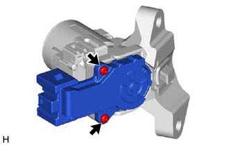
Using a drill, drill a hole in the 2 steering lock set bolts and insert a screw extractor.
-
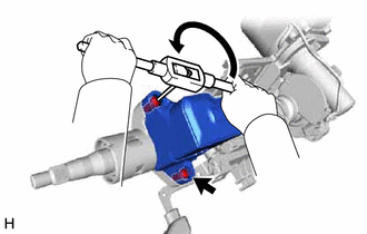
Using the screw extractor, remove the 2 steering lock set bolts and steering lock actuator assembly.
-
-
REMOVE UPPER STEERING COLUMN BRACKET WITH SWITCH ASSEMBLY (w/o Smart Entry and Start System)
Tech Tips
Perform the same procedure as for the steering lock actuator assembly.
-
REMOVE STEERING INTERMEDIATE SHAFT ASSEMBLY
-
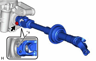
*a Matchmark Remove the bolt and slide the steering intermediate shaft assembly.
Note
Do not separate the steering intermediate shaft assembly from the steering column assembly.
-
Put matchmarks on the steering intermediate shaft assembly and the steering column assembly.
-
Remove the steering intermediate shaft assembly from the steering column assembly.
-
-
REMOVE POWER STEERING ECU PROTECTOR
-
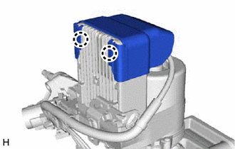
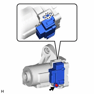
Disengage the 2 claws to remove the power steering ECU protector from the power steering ECU assembly.
-
-
REMOVE ECU WIRE SUB-ASSEMBLY
-
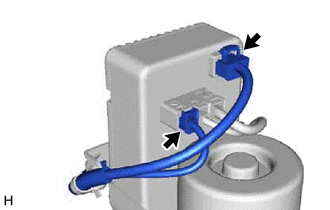
Disconnect the 2 connectors from the power steering ECU assembly.
-
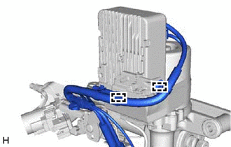
Disengage the 2 wire harness clamps to remove the ECU wire sub-assembly.
-
-
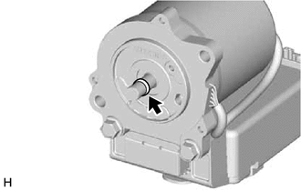
REMOVE POWER STEERING ECU WITH MOTOR ASSEMBLY
-
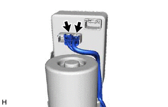
Disconnect the 2 connectors from the power steering ECU assembly.
-
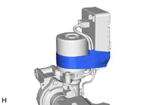
Remove the tape.
-
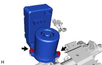
Remove the 2 bolts and power steering ECU with motor assembly from the electric power steering column sub-assembly.
-
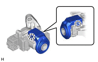
Remove the O-ring from the power steering ECU with motor assembly.
-
-
REMOVE POWER STEERING MOTOR ASSEMBLY
-
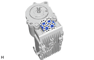
Disengage the 4 claws to remove the No. 2 power steering ECU protector.
-
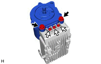
Remove the 3 terminal bolts, 2 bolts and power steering motor assembly from the power steering ECU assembly.
-
-
REMOVE TRANSPONDER KEY COIL (w/o Smart Entry and Start System)
-
Disengage the 2 claws and remove the transponder key coil.
-
-
REMOVE IGNITION OR STARTER SWITCH ASSEMBLY (w/o Smart Entry and Start System)
-
Remove the 2 screws and ignition or starter switch assembly from the upper steering column bracket assembly.
-
-
REMOVE KEY INTERLOCK SOLENOID (w/o Smart Entry and Start System)
-
Remove the screw.
-
Disengage the claw to remove the key interlock solenoid from the upper steering column bracket assembly.
-
-
REMOVE IGNITION SWITCH LOCK CYLINDER ASSEMBLY (w/o Smart Entry and Start System)
-
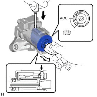
*1 LOCK 
Push 
Pull Turn the ignition switch to ACC.
-
Insert the tip of a screwdriver into the hole in the upper steering column bracket assembly, as shown in the illustration, and pull the ignition switch lock cylinder assembly.
-
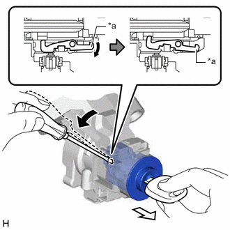
*a Claw Tilt Pull out Insert the tip of a screwdriver into the hole in the upper steering column bracket assembly and tilt it downward, as shown in the illustration, to disengage the claw on the ignition switch lock cylinder assembly. Then pull out the ignition switch lock cylinder assembly.
-
-
REMOVE UN-LOCK WARNING SWITCH ASSEMBLY (w/o Smart Entry and Start System)
-
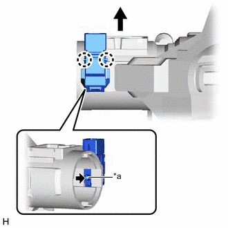
*a Center Part Remove the un-lock warning switch assembly by pushing up the center part and releasing the 2 claws.
Tech Tips
Slide the un-lock warning switch in the direction shown by the arrow in the illustration to remove it.
-