POWER STEERING SYSTEM EPS Warning Light Circuit
DESCRIPTION
If the power steering ECU assembly detects a malfunction, the EPS warning light comes on. At this time, the power steering ECU assembly stores a DTC in its memory.
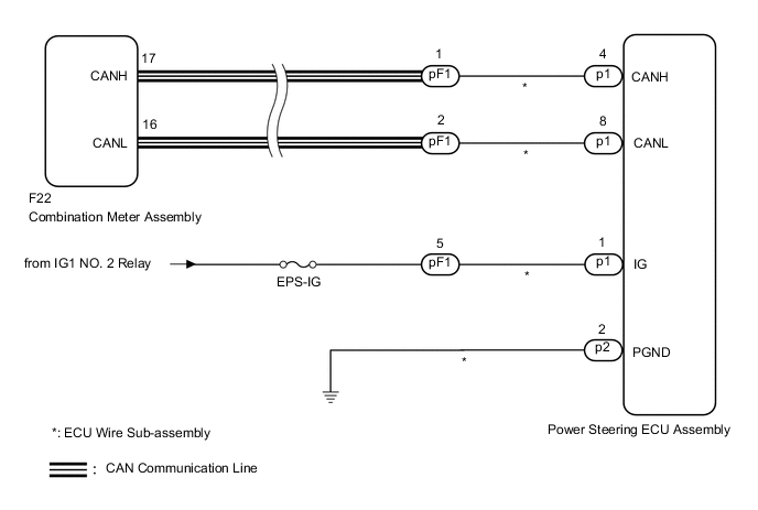
WIRING DIAGRAM
CAUTION / NOTICE / HINT
Tech Tips
Inspect the fuses for circuits related to this system before performing the following procedure.
PROCEDURE
-
CHECK CONNECTOR CONNECTION CONDITION AND GROUND WIRE
-
Check the connection condition of the ECU wire sub-assembly and power steering ECU assembly connectors.
OK The ECU wire sub-assembly and power steering ECU assembly connectors are securely connected. -
Check that the ground wire is securely installed with the bolt.
OK The ground wire is securely installed with the bolt. Result Proceed to OK NG
NG 
CONNECT CONNECTOR OR INSTALL GROUND WIRE Click here
OK 
-
-
CHECK CAN COMMUNICATION SYSTEM
-
Check for DTCs.
Result Result Proceed to CAN communication system DTCs are not output. A CAN communication system DTCs are output. B
B
GO TO CAN COMMUNICATION SYSTEM Click here
A
-
-
CHECK HARNESS AND CONNECTOR (BATTERY - ECU WIRE SUB-ASSEMBLY)
-
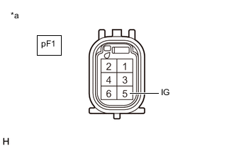
*a Front view of wire harness connector
(to ECU Wire Sub-assembly)
Disconnect the pF1 ECU wire sub-assembly connector.
-
Measure the voltage according to the value(s) in the table below.
Standard Voltage Tester Connection Condition Specified Condition pF1-5 (IG) - Body ground Ignition switch ON 9 to 16 V Result Proceed to OK NG
NG
REPAIR OR REPLACE HARNESS OR CONNECTOR
OK
-
-
CHECK ECU WIRE SUB-ASSEMBLY
-
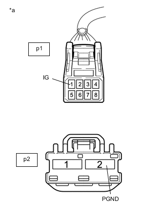
*a Front view of wire harness connector
(to Power Steering ECU Assembly)
Connect the pF1 connector to the ECU wire sub-assembly.
-
Disconnect the p1 and p2 power steering ECU assembly connectors.
-
Measure the voltage according to the value(s) in the table below.
Standard Voltage Tester Connection Condition Specified Condition p1-1 (IG) - Body ground Ignition switch ON 9 to 16 V -
Measure the resistance according to the value(s) in the table below.
Standard Resistance Tester Connection Condition Specified Condition p2-2 (PGND) - Body ground Always Below 1 Ω Result Proceed to OK NG
NG
REPAIR OR REPLACE ECU WIRE SUB-ASSEMBLY Click here
OK
-
-
INSPECT COMBINATION METER ASSEMBLY
-
Reconnect the p1 and p2 power steering ECU assembly connectors.
-
Perform the Active Test of the combination meter assembly using the GTS.
Body Electrical > Combination Meter > Active TestTester Display Indicat. EPS -
Check the combination meter assembly.
OK The EPS warning light turns on or off in accordance with the GTS operation. Tech Tips
If troubleshooting has been carried out according to Problem Symptoms Table, refer back to the table and proceed to the next step before replacing the part.
Result Proceed to OK NG
OK
REPLACE POWER STEERING ECU ASSEMBLY Click here
NG
GO TO METER / GAUGE SYSTEM Click here
-