VACUUM PUMP REMOVAL
PROCEDURE
-
PRECAUTION
Note
After turning the ignition switch off, waiting time may be required before disconnecting the cable from the negative (-) battery terminal. Therefore, make sure to read the disconnecting the cable from the negative (-) battery terminal notices before proceeding with work.
-
DISCONNECT CABLE FROM NEGATIVE BATTERY TERMINAL
Note
When disconnecting the cable, some systems need to be initialized after the cable is reconnected.
-
REMOVE THROTTLE BODY WITH MOTOR ASSEMBLY
-
REMOVE FRONT WHEEL LH
-
REMOVE WINDSHIELD WIPER MOTOR AND LINK ASSEMBLY
-
REMOVE OUTER COWL TOP PANEL SUB-ASSEMBLY
for LHD: Click here
for RHD: Click here
-
REMOVE RADIATOR SIDE DEFLECTOR SEAL LH
-
REMOVE RADIATOR SIDE SEAL RH
-
REMOVE COOL AIR INTAKE DUCT SEAL
-
REMOVE V-BANK COVER SUB-ASSEMBLY
-
REMOVE INLET AIR CLEANER ASSEMBLY
-
REMOVE AIR CLEANER FILTER ELEMENT SUB-ASSEMBLY
-
REMOVE AIR CLEANER CASE SUB-ASSEMBLY
-
SEPARATE TRANSMISSION CONTROL CABLE ASSEMBLY
-
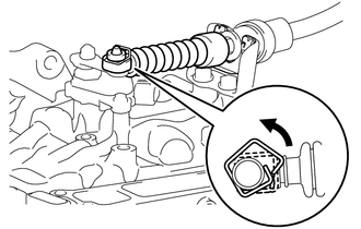
Remove the clip from the transmission control shaft lever as shown in the illustration.
-
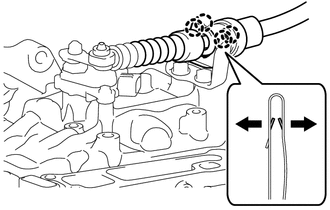
Using a screwdriver, disengage the 4 claws and disconnect the transmission control cable assembly with the clip from the No. 1 transmission control cable bracket.
-
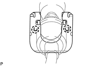
Using a screwdriver, disengage the 2 claws and disconnect the clip from the transmission control cable assembly.
-
-
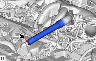
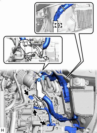
DISCONNECT AIR TUBE
-
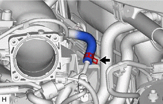
Slide the clip and disconnect the air tube from the vacuum pump assembly.
-
-
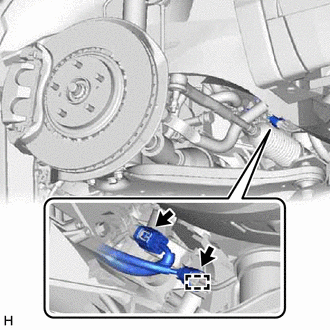
DISCONNECT VENTILATION HOSE
-
Slide the clip and disconnect the ventilation hose.
-
-
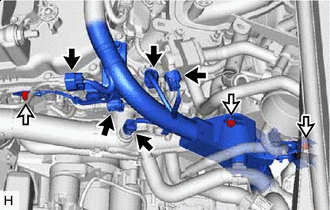
DISCONNECT HEATER WATER HOSE
-
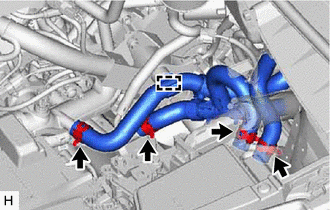
Disengage the clamp.
-
Slide the 4 clips and disconnect the 4 heater water hoses.
-
-
REMOVE NO. 2 ENGINE UNDER COVER
-
SEPARATE ENGINE WIRE
-
Disconnect the 2 connectors.
-
Disengage the clamp.
-
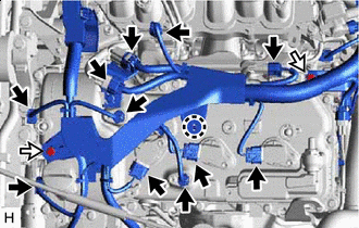

Connector 
Bolt Disconnect the 11 connectors.
-
Disengage the claw.
-
Remove the 2 bolts.
-
Connector Bolt Disconnect the 5 connectors.
-
Remove the 3 bolts.
-
Connector Bolt 
Nut Disengage the clamp.
-
Disconnect the 3 connectors.
-
Remove the 2 bolts and nut to separate the engine wire.
-
-
REMOVE VACUUM PUMP ASSEMBLY
-
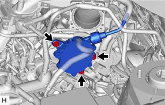
Remove the 3 bolts and vacuum pump assembly from the engine assembly.
-
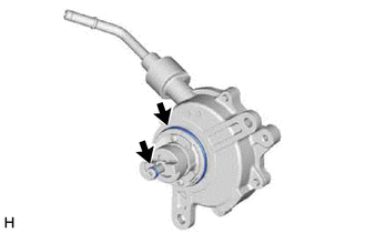
Remove the 2 O-rings from the vacuum pump assembly.
-