BRAKE BOOSTER(for RHD) INSTALLATION
PROCEDURE
-
INSTALL BRAKE BOOSTER GASKET
-
Install a new brake booster gasket to the brake booster assembly.
-
-
INSTALL BRAKE BOOSTER ASSEMBLY
-
Temporarily install the brake booster assembly to the vehicle body.
-
Temporarily install the lock nut and brake master cylinder push rod clevis to the brake booster assembly.
Note
Fully tighten the lock nut when adjusting the brake pedal height.
-
Install the 4 nuts to secure the brake booster assembly.
- Torque:
- 12.7 N*m { 130 kgf*cm, 9 ft.*lbf }
-
-
INSTALL PUSH ROD PIN
-
INSTALL BRAKE PEDAL RETURN SPRING
-
INSTALL CYLINDER HEAD COVER SUB-ASSEMBLY
-
INSTALL OIL PIPE
-
INSTALL NO. 2 TIMING GEAR COVER
-
INSTALL FUEL HOSE PROTECTOR
-
INSTALL IGNITION COIL ASSEMBLY
-
Install the 3 ignition coil assemblies with the 3 bolts.
- Torque:
- 10 N*m { 102 kgf*cm, 7 ft.*lbf }
-
-
INSTALL ENGINE WIRE
-
Install the engine wire to the cylinder head cover sub-assembly with the bolt.
-
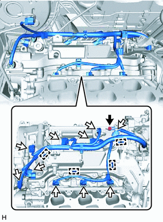

Bolt 
Connector Install the bolt, engage the 4 clamps and connect the 10 connectors.
- Torque:
- 8.5 N*m { 87 kgf*cm, 75 in.*lbf }
-
-
INSTALL HOSE BRACKET
-
Install the hose bracket with the bolt.
- Torque:
- 7.8 N*m { 80 kgf*cm, 69 in.*lbf }
-
Engage the clamp to install the engine wire.
-
-
CONNECT NO. 2 VENTILATION HOSE
-
Connect the No. 2 ventilation hose to the cylinder head cover sub-assembly and slide the clip to secure it.
-
-
INSTALL NO. 1 SURGE TANK STAY
-
INSTALL THROTTLE BODY BRACKET
-
INSTALL INTAKE AIR SURGE TANK ASSEMBLY
-
INSTALL THROTTLE BODY GASKET
-
INSTALL THROTTLE BODY WITH MOTOR ASSEMBLY
-
INSTALL BRAKE LINE
-
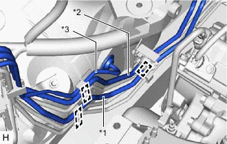
*1 Front No. 6 Brake Tube *2 Front No. 7 Brake Tube *3 Front No. 8 Brake Tube Install the front No. 6 brake tube and front No. 7 brake tube, and engage the 3 clamps to secure the 3 brake lines.
Note
-
Do not damage the 3 clamps.
-
Do not kink or damage the brake lines.
Tech Tips
Install the front No. 6 brake tube and front No. 7 brake tube while avoiding the front No. 8 brake tube.
-
-
Engage the clamp to secure the 3 brake lines.
Note
-
Do not damage the clamp.
-
Do not kink or damage the brake lines.
-
-
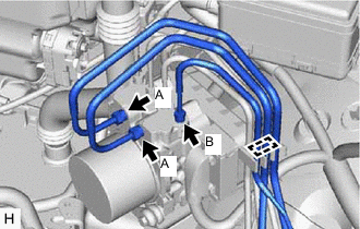
Using a union nut wrench, connect the 3 brake lines to the brake actuator assembly.
- Torque:
- Brake Line (A)
- 19.5 N*m { 199 kgf*cm, 14 ft.*lbf }
- Brake Line (B)
- 15.2 N*m { 155 kgf*cm, 11 ft.*lbf }
Note
-
Do not kink or damage the brake lines.
-
Do not allow the brake lines to twist or interfere with other parts or the vehicle body during tightening.
-
Do not allow any foreign matter such as dirt or dust to enter the brake lines from the connecting parts.
-
Use the formula to calculate special torque values for situations where the union nut wrench is combined with a torque wrench.
-
-
CONNECT SUCTION HOSE SUB-ASSEMBLY
-
Remove the vinyl tape from the suction hose sub-assembly.
-
Sufficiently apply compressor oil to 2 new O-rings and the fitting surface of the suction hose sub-assembly.
Compressor Oil ND-OIL 8 or equivalent -
Install the 2 O-rings to the suction hose sub-assembly
-
Connect the suction hose sub-assembly to the No. 1 air conditioning accessory assembly.
Note
Do not deform the refrigerant lines.
-
Install the piping clamp to the suction hose sub-assembly.
-
-
INSTALL AIR CONDITIONER TUBE AND ACCESSORY ASSEMBLY
-
Remove the vinyl tape from the air conditioner tube and accessory assembly.
-
Sufficiently apply compressor oil to a new O-ring and the fitting surface of the air conditioner tube and accessory assembly.
Compressor Oil ND-OIL 8 or equivalent -
Install the O-ring to the air conditioner tube and accessory assembly.
-
Insert the air conditioner tube and accessory assembly to the air conditioning unit assembly.
-
Install the air conditioner tube and accessory assembly with the nut.
- Torque:
- 9.8 N*m { 100 kgf*cm, 87 in.*lbf }
Note
Do not deform the refrigerant lines.
-
Install the air conditioner tube and accessory assembly with the bolt.
- Torque:
- 9.8 N*m { 100 kgf*cm, 87 in.*lbf }
Note
Do not deform the refrigerant lines.
-
Engage the clamp to install the air conditioner tube and accessory assembly to the brake actuator assembly.
Note
-
Do not deform the refrigerant lines.
-
Do not damage the clamp.
-
-
Engage the clamp to install the air conditioner tube and accessory assembly.
Note
-
Do not deform the refrigerant lines.
-
Do not damage the clamp.
-
-
-
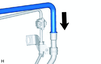
INSTALL SUCTION HOSE SUB-ASSEMBLY
-
Remove the vinyl tape from the suction hose sub-assembly.
-
Sufficiently apply compressor oil to a new O-ring and the fitting surface of the suction hose sub-assembly.
Compressor Oil ND-OIL 8 or equivalent -
Install the O-ring to the suction hose sub-assembly.
-
Insert the suction hose sub-assembly to the air conditioning unit assembly.
-
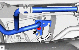
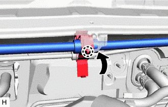
Rotate the hook connector as shown in the illustration.
-
Insert the tube joint into the fitting hole securely and install the bolt.
- Torque:
- 9.8 N*m { 100 kgf*cm, 87 in.*lbf }
-
Install the suction hose sub-assembly to the piping clamp.
Note
-
Do not deform the refrigerant lines.
-
Do not damage the clamp.
-
-
Engage the claw to lock the piping clamp.
-
Install the suction hose sub-assembly to the suction hose clamp, and engage the claw to secure it.
Note
-
Do not deform the refrigerant lines.
-
Do not damage the clamp.
-
-
Engage the clamp to install the suction hose sub-assembly to the brake actuator assembly.
Note
-
Do not deform the refrigerant lines.
-
Do not damage the clamp.
-
-
Engage the clamp to install the suction hose sub-assembly.
Note
-
Do not deform the refrigerant lines.
-
Do not damage the clamp.
-
-
-
INSTALL ENGINE MOVING CONTROL ROD BRACKET
-
INSTALL NO. 2 ENGINE MOUNTING STAY RH
-
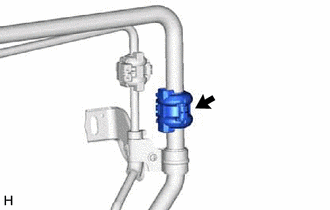
CONNECT UNION TO CHECK VALVE HOSE
-
Connect the union to check valve hose to the brake booster assembly, and slide the clip to secure it.
-
-
INSTALL RESERVOIR BRACKET
-
Install the reservoir bracket with the 2 nuts.
- Torque:
- 19 N*m { 194 kgf*cm, 14 ft.*lbf }
-
Engage the clamp to install the engine room main wire.
-
-
INSTALL BRAKE MASTER CYLINDER RESERVOIR ASSEMBLY
-
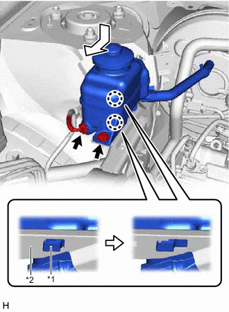
*1 Brake Master Cylinder Reservoir Assembly *2 Reservoir Bracket Move the brake master cylinder reservoir assembly as shown in the illustration to engage the 2 claws.
-
Connect the reservoir level switch connector and install the bolt.
- Torque:
- 9.0 N*m { 92 kgf*cm, 80 in.*lbf }
-
-
INSTALL ENGINE ROOM MAIN WIRE
-
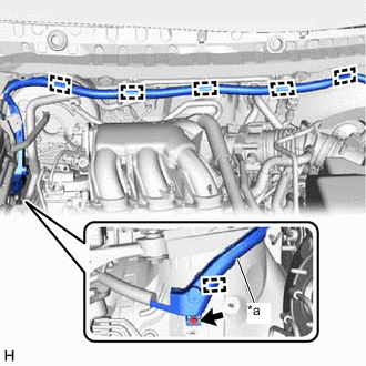
*a Wire Harness Protector Engage the 5 clamps to install the engine room main wire.
-
Engage the clamp to install the wire harness protector.
-
Install the bolt to secure the wire harness protector.
-
-
INSTALL AIR CLEANER FILTER ELEMENT SUB-ASSEMBLY
-
INSTALL AIR CLEANER CAP WITH AIR CLEANER HOSE
-
CONNECT CABLE TO NEGATIVE BATTERY TERMINAL
Note
When disconnecting the cable, some systems need to be initialized after the cable is reconnected
-
INSTALL BRAKE MASTER CYLINDER SUB-ASSEMBLY WITH WAY
-
ADD ENGINE COOLANT
-
CHARGE AIR CONDITIONING SYSTEM WITH REFRIGERANT
-
WARM UP ENGINE
-
INSPECT FOR REFRIGERANT LEAK
-
INSPECT FOR COOLANT LEAK
-
INSPECT ENGINE COOLANT LEVEL IN RESERVOIR TANK
-
INSPECT AND ADJUST BRAKE PEDAL
-
INSTALL V-BANK COVER SUB-ASSEMBLY
-
INSTALL FRONT WHEEL RH
- Torque:
- 103 N*m { 1050 kgf*cm, 76 ft.*lbf }