BRAKE BOOSTER(for LHD) REMOVAL
CAUTION / NOTICE / HINT
Note
Make sure to release vacuum from the brake booster assembly before removing the brake master cylinder sub-assembly from the brake booster assembly.
PROCEDURE
-
PRECAUTION
Note
After turning the ignition switch off, waiting time may be required before disconnecting the cable from the negative (-) battery terminal. Therefore, make sure to read the disconnecting the cable from the negative (-) battery terminal notices before proceeding with work.
-
REMOVE BRAKE MASTER CYLINDER SUB-ASSEMBLY WITH WAY
-
REMOVE WINDSHIELD WIPER MOTOR AND LINK ASSEMBLY
-
REMOVE OUTER COWL TOP PANEL SUB-ASSEMBLY
-
REMOVE BRAKE MASTER CYLINDER RESERVOIR ASSEMBLY
-
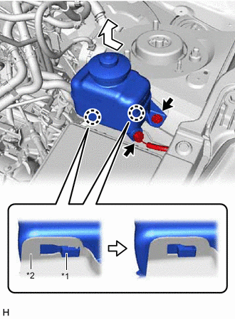
*1 Brake Master Cylinder Reservoir Assembly *2 Reservoir Bracket Disconnect the reservoir level switch connector and remove the bolt from the brake master cylinder reservoir assembly.
-
Move the brake master cylinder reservoir assembly as shown in the illustration to disengage the 2 claws, and remove it.
-
-
REMOVE RESERVOIR BRACKET
-

Remove the 2 bolts and reservoir bracket.
-
-
REMOVE ECM
for 1AR-FE: Click here
for 2GR-FKS: Click here
-
DISCONNECT UNION TO CHECK VALVE HOSE (for 2GR-FKS)
-

Slide the clip and disconnect the union to check valve hose from the brake booster assembly.
-
Separate the union to check valve hose from the engine room main wire.
-
-
SEPARATE ENGINE WIRE (for 1AR-FE)
-

Disengage the 3 clamps to separate the engine wire.
-
-
SEPARATE ENGINE WIRE (for 2GR-FKS)
-

Disengage the 2 clamps to separate the engine wire.
-
-
SEPARATE ENGINE ROOM MAIN WIRE
-

Disengage the 5 clamps to separate the engine room main wire.
-
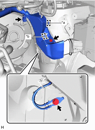
*a Clamp *b Pin for 2GR-FKS:
-
Disconnect the connector from the vacuum warning switch assembly.
-
-
Remove the 2 bolts.
-
Disengage the clamp and pin to separate the wire harness protector.
-

Remove the 2 bolts.
-
Disengage the 2 pins to separate the engine room relay block assembly.
-
-
DISCONNECT FUEL VAPOR FEED HOSE ASSEMBLY
-

Slide the clip and disconnect the fuel vapor feed hose assembly.
-
-
DISCONNECT NO. 1 VACUUM HOSE CONNECTOR (for 1AR-FE)
-

Slide the clip and disconnect the union to check valve hose from the brake booster assembly.
-

Remove the 2 nuts and separate the No. 1 vacuum hose connector.
-
-
SEPARATE SUCTION HOSE SUB-ASSEMBLY
-
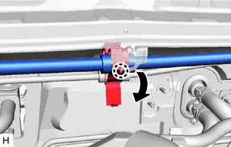
Disengage the claw to release the piping clamp.
-
Separate the suction hose sub-assembly from the piping clamp.
Note
-
Do not deform the refrigerant lines.
-
Do not damage the clamp.
-
-
-
SEPARATE AIR CONDITIONER TUBE AND ACCESSORY ASSEMBLY
-

Remove the nut and separate the air conditioner tube and accessory assembly.
Note
-
Do not deform the refrigerant lines.
-
Do not damage the clamp.
-
-
-
SEPARATE BRAKE LINE
-

*1 Front No. 1 Brake Tube Way Remove the bolt and separate the front No. 1 brake tube way.
-
Disengage the brake tube clamp to separate the 3 brake lines.
Note
-
Do not kink or damage the brake lines.
-
Do not damage the clamp.
-
-
-
REMOVE BRAKE PEDAL RETURN SPRING
-
LOOSEN LOCK NUT
-

*1 Lock Nut *2 Brake Master Cylinder Push Rod Clevis Loosen the lock nut of the brake master cylinder push rod clevis.
-
-
REMOVE PUSH ROD PIN
-
REMOVE BRAKE BOOSTER ASSEMBLY
-

Remove the 4 nuts and push the brake booster assembly toward the engine compartment.
Note
Do not apply excessive force to the brake lines or refrigerant lines.
-
Remove the brake master cylinder push rod clevis and lock nut from the brake booster assembly.
-
Remove the brake booster assembly from the vehicle body.
Note
Do not apply excessive force to the brake lines or refrigerant lines.
-
-
REMOVE BRAKE BOOSTER GASKET