VEHICLE STABILITY CONTROL SYSTEM Downhill Assist Control Indicator Light Remains ON
DESCRIPTION
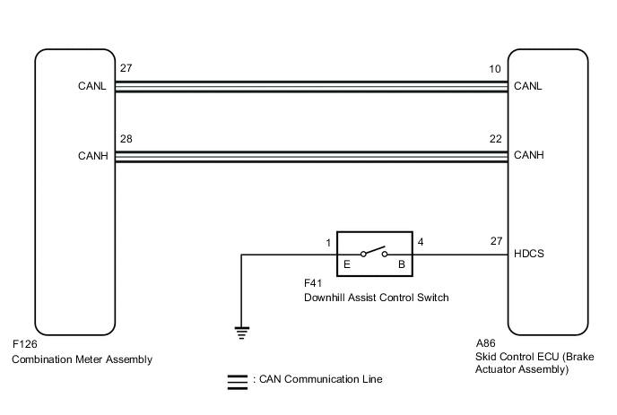
The skid control ECU (brake actuator assembly) is connected to the combination meter assembly via CAN communication.
The downhill assist control indicator light comes on when the downhill assist control is ready. Even if the downhill assist control switch is pressed, the downhill assist control indicator light will blink and the downhill assist control will not be activated under the following conditions:
-
The shift lever is in any position other than S (1st) or R.
-
VSC system is malfunctioning.
-
Temperature of the brake actuator assembly increases and the downhill assist control is temporarily canceled.
WIRING DIAGRAM
CAUTION / NOTICE / HINT
Note
When replacing the skid control ECU (brake actuator assembly), perform zero point calibration and store system information.
PROCEDURE
-
CHECK DTC
-
Check if ABS and/or VSC system DTCs are output.
Chassis > ABS/VSC/TRC > Trouble CodesTech Tips
If the downhill assist control switch is turned on when ABS and/or VSC system DTCs are output, the downhill assist control indicator light blinks and the downhill assist control does not operate.
Result Result Proceed to ABS and/or VSC system DTCs are not output. A ABS and/or VSC system DTCs are output. B
B 
REPAIR CIRCUITS INDICATED BY OUTPUT DTCS Click here
A 
-
-
CHECK DOWNHILL ASSIST CONTROL INDICATOR LIGHT
-
Interview the customer to check if the downhill assist control indicator light was blinking when the downhill assist control was operating.
Tech Tips
-
If the downhill assist control switch is turned on when the shift lever is in any position other than S (1st) or R, the downhill assist control indicator light blinks and the downhill assist control does not operate.
-
If the downhill assist control switch is turned on when the brake actuator assembly is hot, the downhill assist control indicator light blinks and the downhill assist control does not operate.
OK The downhill assist control indicator light does not blink. Result Proceed to OK NG -
NG
END
OK
-
-
CHECK CAN COMMUNICATION SYSTEM
-
Check if CAN communication system DTCs are output.
Result Result Proceed to DTCs are not output. A DTCs are output. B
B
INSPECT CAN COMMUNICATION SYSTEM Click here
A
-
-
CHECK IF BRAKE ACTUATOR ASSEMBLY CONNECTOR IS SECURELY CONNECTED
-
Check if the skid control ECU (brake actuator assembly) connector is securely connected.
OK The connector is securely connected. Result Proceed to OK NG
NG
CONNECT CONNECTOR TO BRAKE ACTUATOR ASSEMBLY CORRECTLY
OK
-
-
CHECK BATTERY
-
Check the battery voltage.
Standard Voltage Tester Connection Condition Specified Condition Battery Always 11 to 14 V Result Proceed to OK NG
NG
CHECK OR REPLACE CHARGING SYSTEM OR BATTERY for 1AR-FE: Click here
CHECK OR REPLACE CHARGING SYSTEM OR BATTERY for 2GR-FKS: Click hereOK
-
-
READ VALUE USING GTS (DOWNHILL ASSIST CONTROL SWITCH)
-
Connect the GTS to the DLC3.
-
Turn the ignition switch to ON.
-
Select the Data List using the GTS.
Chassis > ABS/VSC/TRC > Data ListTester Display Measurement Item Range Normal Condition Diagnostic Note Downhill Assist Control SW Downhill assist control switch ON or OFF ON: Switch on
OFF: Switch off
for AWD
Chassis > ABS/VSC/TRC > Data ListTester Display Downhill Assist Control SW -
Using the GTS, check the switch condition on the GTS changes according to downhill assist control switch operation.
OK The GTS display changes according to downhill assist control switch operation. Result Proceed to OK NG
NG 
INSPECT DOWNHILL ASSIST CONTROL SWITCH Click here
OK
-
-
READ VALUE USING GTS (DOWNHILL ASSIST CONTROL INDICATOR LIGHT)
-
Select the Data List on the GTS.
Chassis > ABS/VSC/TRC > Data ListTester Display Measurement Item Range Normal Condition Diagnostic Note Downhill Assist Control Light Downhill assist control indicator light ON or OFF ON: Indicator light on
OFF: Indicator light off
for AWD
Chassis > ABS/VSC/TRC > Data ListTester Display Downhill Assist Control Light -
Check the GTS display condition of the downhill assist control indicator light.
Result Result Proceed to Display of the Data List remains ON. A Display of the Data List remains OFF. B Tech Tips
If troubleshooting has been carried out according to Problem Symptoms Table, refer back to the table and proceed to the next step before replacing parts.
A
REPLACE BRAKE ACTUATOR ASSEMBLY Click here
B
INSPECT METER / GAUGE SYSTEM Click here
-
-
INSPECT DOWNHILL ASSIST CONTROL SWITCH
-
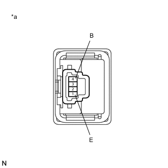
*a Component without harness connected
(Downhill Assist Control Switch)
Turn the ignition switch off.
-
Disconnect the F41 Downhill assist control switch connector.
-
Measure the resistance according to the value(s) in the table below.
Standard Resistance Tester Connection Condition Specified Condition 4 (B) - 1 (E) Downhill assist control switch pushed Below 1 Ω 4 (B) - 1 (E) Downhill assist control switch not pushed 10 kΩ or higher Result Proceed to OK NG
NG
REPLACE DOWNHILL ASSIST CONTROL SWITCH Click here
OK
-
-
CHECK HARNESS AND CONNECTOR (BRAKE ACTUATOR ASSEMBLY - DOWNHILL ASSIST CONTROL SWITCH)
-
Disconnect the A86 skid control ECU (brake actuator assembly) connector.
-
Measure the resistance according to the value(s) in the table below.
Standard Resistance Tester Connection Condition Specified Condition A86-27 (HDCS) - F41-4 (B) Always Below 1 Ω A86-27 (HDCS) or F41-4 (B) - Body ground Always 10 kΩ or higher F41-1 (E) - Body ground Always Below 1 Ω Tech Tips
If troubleshooting has been carried out according to Problem Symptoms Table, refer back to the table and proceed to the next step before replacing parts.
Result Proceed to OK NG
OK
REPLACE BRAKE ACTUATOR ASSEMBLY Click here
NG
REPAIR OR REPLACE HARNESS OR CONNECTOR
-