VEHICLE STABILITY CONTROL SYSTEM, Diagnostic DTC:C1426

| DTC Code | DTC Name |
|---|---|
| C1426 | Stop Light Switch OFF Stuck Malfunction |
DESCRIPTION
The skid control ECU (brake actuator assembly) receives stop light switch signals and uses them to determine whether or not the brakes are applied.
The skid control ECU (brake actuator assembly) has a detection circuit that it uses to detect an open in the stop light input line.
If the skid control ECU (brake actuator assembly) detects an open in this circuit, it will store this DTC.
| DTC No. | Detection Item | DTC Detection Condition | Trouble Area |
|---|---|---|---|
| C1426 | Stop Light Switch OFF Stuck Malfunction | When the brake pedal load sensing switch is on, the master cylinder pressure is 2 MPa (20.4 kgf/cm2, 290 psi) or more and the deceleration calculated from the vehicle speed is 0.2 G or more, the stop light switch assembly is off for 2 seconds or more. |
|
CAUTION / NOTICE / HINT
Note
-
When replacing the skid control ECU (brake actuator assembly), perform zero point calibration and store system information.
-
Inspect the fuses for circuits related to this system before performing the following procedure.
PROCEDURE
-
CHECK BRAKE PEDAL HEIGHT AND STOP LIGHT SWITCH ASSEMBLY INSTALLATION
-
Check the brake pedal height and stop light switch assembly installation.
for LHD: Click here
for RHD: Click here
OK The brake pedal height and stop light switch assembly installation are normal. Tech Tips
If the on/off status of the stop light switch assembly and the pressure increase information from the master cylinder pressure sensor do not match due to an improperly installed brake pedal or stop light switch assembly, this DTC may be stored. Therefore, be sure to check the installation condition of the pedal and stop light switch assembly before inspecting the input signals and other related parts.
Result Proceed to OK NG
NG 
ADJUST BRAKE PEDAL HEIGHT OR STOP LIGHT SWITCH ASSEMBLY INSTALLATION for LHD: Click here
ADJUST BRAKE PEDAL HEIGHT OR STOP LIGHT SWITCH ASSEMBLY INSTALLATION for RHD: Click hereOK 
-
-
CHECK STOP LIGHT OPERATION
-
Check that the stop lights come on when the brake pedal is depressed, and go off when the brake pedal is released.
OK Condition Illumination Condition Brake pedal depressed. On Brake pedal released. Off Result Proceed to OK NG
NG 
INSPECT STOP LIGHT SWITCH ASSEMBLY Click here
OK
-
-
READ VALUE USING GTS (STOP LIGHT SWITCH ASSEMBLY AND BRAKE PEDAL LOAD SENSING SWITCH)
-
Connect the GTS to the DLC3.
-
Turn the ignition switch to ON.
-
Select the Data List using the GTS.
Chassis > ABS/VSC/TRC > Data ListTester Display Measurement Item Range Normal Condition Diagnostic Note Stop Light SW Stop light switch assembly ON or OFF ON: Brake pedal depressed
OFF: Brake pedal released
- Brake Pedal Load Sensing SW Brake pedal load sensing switch ON or OFF ON: Brake pedal depressed beyond a specified point
OFF: Brake pedal not depressed beyond a specified point
-
Chassis > ABS/VSC/TRC > Data ListTester Display Stop Light SW Brake Pedal Load Sensing SW -
Check that the stop light switch display and brake pedal load sensing switch display observed on the GTS change according to brake pedal operation.
OK The GTS displays ON or OFF according to brake pedal operation. -
Slowly depress the brake pedal, and check when the stop light switch assembly and brake pedal load sensing switch turn on.
OK First the stop light switch assembly should turn on, and then the brake pedal load sensing switch should turn on. Result Result Proceed to OK A NG (The stop light switch assembly does not turn on.) B NG (Turning on of the brake pedal load sensing switch is not confirmed.) C NG (The brake pedal load sensing switch turns on first.) D
B
CHECK HARNESS AND CONNECTOR (STP TERMINAL) Click here
C
INSPECT BRAKE PEDAL SUPPORT ASSEMBLY Click here
D
REPLACE BRAKE PEDAL SUPPORT ASSEMBLY Click here
A
-
-
RECONFIRM DTC
-
Turn the ignition switch off.
-
Clear the DTCs.
Chassis > ABS/VSC/TRC > Clear DTCs -
Turn the ignition switch off.
-
Start the engine.
-
Depress the brake pedal several times to test the stop light circuit.
-
Check if the same DTC is output.
Chassis > ABS/VSC/TRC > Trouble CodesResult Result Proceed to DTC C1426 is not output. A DTC C1426 is output. B Tech Tips
If troubleshooting has been carried out according to Problem Symptoms Table, refer back to the table and proceed to the next step before replacing parts.
A
USE SIMULATION METHOD TO CHECK Click here
B
REPLACE BRAKE ACTUATOR ASSEMBLY Click here
-
-
CHECK HARNESS AND CONNECTOR (STP TERMINAL)
-
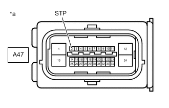
*a Front view of wire harness connector
(to Skid Control ECU (Brake Actuator Assembly))
Turn the ignition switch off.
-
Make sure that there is no looseness at the locking part and the connecting part of the connector.
-
Disconnect the A47 skid control ECU (brake actuator assembly) connector.
-
Measure the voltage according to the value(s) in the table below.
Standard Voltage Tester Connection Condition Specified Condition A47-2 (STP) - Body ground Stop light switch assembly ON (Brake pedal depressed) 8 to 14 V A47-2 (STP) - Body ground Stop light switch assembly OFF (Brake pedal released) Below 1.5 V Result Proceed to OK NG
NG
REPAIR OR REPLACE HARNESS OR CONNECTOR (STP CIRCUIT)
OK
-
-
CHECK HARNESS AND CONNECTOR (GND1 TERMINAL)
-
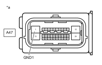
*a Front view of wire harness connector
(to Skid Control ECU (Brake Actuator Assembly))
Measure the resistance according to the value(s) in the table below.
Standard Resistance Tester Connection Condition Specified Condition A47-1 (GND1) - Body ground Always Below 1 Ω Tech Tips
If troubleshooting has been carried out according to Problem Symptoms Table, refer back to the table and proceed to the next step before replacing parts.
Result Proceed to OK NG
OK
REPLACE BRAKE ACTUATOR ASSEMBLY Click here
NG
REPAIR OR REPLACE HARNESS OR CONNECTOR (GND1 CIRCUIT)
-
-
INSPECT BRAKE PEDAL SUPPORT ASSEMBLY
-
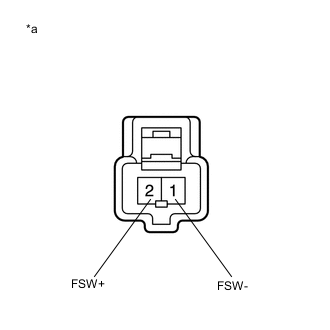
*a Component without harness connected
(Brake Pedal Load Sensing Switch (Brake Pedal Support Assembly))
Turn the ignition switch off.
-
Make sure that there is no looseness at the locking part and the connecting part of the connector.
-
Disconnect the A55 or A56 brake pedal load sensing switch (brake pedal support assembly) connector.
Note
-
Do not remove the brake pedal load sensing switch from the brake pedal support assembly.
-
When there is a malfunction in the brake pedal load sensing switch, replace the brake pedal support assembly.
-
-
Measure the resistance according to the value(s) in the table below.
Standard Resistance Tester Connection Condition Specified Condition 2 (FSW+) - 1 (FSW-) Switch OFF (Brake pedal depressed) 950 to 1050 Ω 2 (FSW+) - 1 (FSW-) Switch ON (Brake pedal released) 203 to 223 Ω Result Proceed to OK NG
NG
REPLACE BRAKE PEDAL SUPPORT ASSEMBLY for LHD: Click here
REPLACE BRAKE PEDAL SUPPORT ASSEMBLY for RHD: Click hereOK
-
-
CHECK HARNESS AND CONNECTOR (BRAKE ACTUATOR ASSEMBLY - BRAKE PEDAL SUPPORT ASSEMBLY)
-
Make sure that there is no looseness at the locking part and the connecting part of the connector.
-
Disconnect the A47 skid control ECU (brake actuator assembly) connector.
-
Measure the resistance according to the value(s) in the table below.
Standard Resistance for LHD Tester Connection Condition Specified Condition A47-27 (FSW+) - A56-2 (FSW+) Always Below 1 Ω A47-27 (FSW+) or A56-2 (FSW+) - Body ground Always 10 kΩ or higher A56-1 (FSW-) - Body ground Always Below 1 Ω for RHD Tester Connection Condition Specified Condition A47-27 (FSW+) - A55-2 (FSW+) Always Below 1 Ω A47-27 (FSW+) or A55-2 (FSW+) - Body ground Always 10 kΩ or higher A55-1 (FSW-) - Body ground Always Below 1 Ω Tech Tips
If troubleshooting has been carried out according to Problem Symptoms Table, refer back to the table and proceed to the next step before replacing parts.
Result Proceed to OK NG
OK
REPLACE BRAKE ACTUATOR ASSEMBLY Click here
NG
REPAIR OR REPLACE HARNESS OR CONNECTOR
-
-
INSPECT STOP LIGHT SWITCH ASSEMBLY
-
Check the stop light switch assembly.
OK The stop light switch assembly is normal. Result Result Proceed to OK (w/ Downhill assist control or dynamic radar cruise control) A OK (w/o Downhill assist control or dynamic radar cruise control) B NG C
B
CHECK HARNESS AND CONNECTOR (STP TERMINAL) Click here
C
REPLACE STOP LIGHT SWITCH ASSEMBLY Click here
A
-
-
CHECK HARNESS AND CONNECTOR (SWITCH INPUT TERMINAL)
-
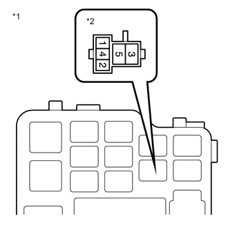
*1 NO. 1 Engine Room Relay Block and NO. 1 Junction Block Assembly *2 Stop Light Control Relay (STOP LP Relay) Turn the ignition switch off.
-
Remove the stop light control relay (STOP LP relay).
-
Measure the voltage according to the value(s) in the table below.
Standard Voltage Tester Connection Condition Specified Condition Stop light control relay (STOP LP relay) terminal 4 - Body ground Stop light switch assembly ON (Brake pedal depressed) 8 to 14 V Stop light control relay (STOP LP relay) terminal 4 - Body ground Stop light switch assembly OFF (Brake pedal released) Below 1.5 V Result Proceed to OK NG
NG
REPAIR OR REPLACE HARNESS OR CONNECTOR (SWITCH INPUT CIRCUIT)
OK
-
-
INSPECT STOP LIGHT CONTROL RELAY
-
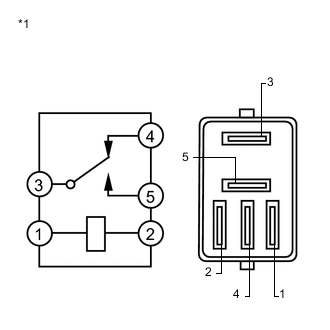
*1 Stop Light Control Relay (STOP LP Relay) Measure the resistance according to the value(s) in the table below.
Standard Resistance Tester Connection Condition Specified Condition 3 - 4 Voltage is not applied between terminals 1 and 2 Below 1 Ω 3 - 4 Voltage is applied between terminals 1 and 2 10 kΩ or higher Result Proceed to OK NG
NG
REPLACE STOP LIGHT CONTROL RELAY
OK
-
-
CHECK HARNESS AND CONNECTOR (STP TERMINAL)
-
*a Front view of wire harness connector
(to Skid Control ECU (Brake Actuator Assembly))
Turn the ignition switch off.
-
Install the stop light control relay (STOP LP relay).
-
Make sure that there is no looseness at the locking part and the connecting part of the connector.
-
Disconnect the A47 skid control ECU (brake actuator assembly) connector.
-
Measure the voltage according to the value(s) in the table below.
Standard Voltage Tester Connection Condition Specified Condition A47-2 (STP) - Body ground Stop light switch assembly ON (Brake pedal depressed) 8 to 14 V A47-2 (STP) - Body ground Stop light switch assembly OFF (Brake pedal released) Below 1.5 V Result Proceed to OK NG
NG
REPAIR OR REPLACE HARNESS OR CONNECTOR (STP CIRCUIT)
OK
-
-
RECONFIRM DTC
-
Turn the ignition switch off.
-
Reconnect the A47 skid control ECU (brake actuator assembly) connector.
-
Clear the DTCs.
Chassis > ABS/VSC/TRC > Clear DTCs -
Turn the ignition switch off.
-
Start the engine.
-
Depress the brake pedal several times to test the stop light circuit.
-
Check if the same DTC is output.
Chassis > ABS/VSC/TRC > Trouble CodesResult Result Proceed to DTC C1426 is not output. A DTC C1426 is output. B Tech Tips
-
If the lighting system is normal but the DTC is still output, replace the skid control ECU (brake actuator assembly).
-
If troubleshooting has been carried out according to Problem Symptoms Table, refer back to the table and proceed to the next step before replacing parts.
-
A
USE SIMULATION METHOD TO CHECK Click here
B
INSPECT LIGHTING SYSTEM (STOP LIGHT CIRCUIT) Click here
-
-
CHECK HARNESS AND CONNECTOR (STP TERMINAL)
-
*a Front view of wire harness connector
(to Skid Control ECU (Brake Actuator Assembly))
Make sure that there is no looseness at the locking part and the connecting part of the connector.
-
Disconnect the A47 skid control ECU (brake actuator assembly) connector.
-
Measure the voltage according to the value(s) in the table below.
Standard Voltage Tester Connection Condition Specified Condition A47-2 (STP) - Body ground Stop light switch assembly ON (Brake pedal depressed) 8 to 14 V A47-2 (STP) - Body ground Stop light switch assembly OFF (Brake pedal released) Below 1.5 V Result Proceed to OK NG
NG
REPAIR OR REPLACE HARNESS OR CONNECTOR (STP CIRCUIT)
OK
-
-
RECONFIRM DTC
-
Turn the ignition switch off.
-
Reconnect the A47 skid control ECU (brake actuator assembly) connector.
-
Clear the DTCs.
Chassis > ABS/VSC/TRC > Clear DTCs -
Turn the ignition switch off.
-
Start the engine.
-
Depress the brake pedal several times to test the stop light circuit.
-
Check if the same DTC is output.
Chassis > ABS/VSC/TRC > Trouble CodesResult Result Proceed to DTC C1426 is not output. A DTC C1426 is output. B Tech Tips
-
If the lighting system is normal but the DTC is still output, replace the skid control ECU (brake actuator assembly).
-
If troubleshooting has been carried out according to Problem Symptoms Table, refer back to the table and proceed to the next step before replacing parts.
-
A
USE SIMULATION METHOD TO CHECK Click here
B
INSPECT LIGHTING SYSTEM (STOP LIGHT CIRCUIT) Click here
-