VEHICLE STABILITY CONTROL SYSTEM, Diagnostic DTC:C1380

| DTC Code | DTC Name |
|---|---|
| C1380 | Stop Light Control Relay Malfunction |
DESCRIPTION
Upon receiving the downhill assist control (for AWD) or dynamic radar cruise control (w/ dynamic radar cruise control) operating signal from the skid control ECU (brake actuator assembly), the stop light control relay contact turns on and the stop light comes on.
| DTC No. | Detection Item | DTC Detection Condition | Trouble Area |
|---|---|---|---|
| C1380 | Stop Light Control Relay Malfunction | Either of the following is detected:
|
|
CAUTION / NOTICE / HINT
Note
-
When replacing the skid control ECU (brake actuator assembly), perform zero point calibration and store system information.
-
Inspect the fuses for circuits related to this system before performing the following procedure.
Tech Tips
When C1425 and/or C1426 is output together with C1380, inspect and repair the trouble areas indicated by C1425 and/or C1426 first.
for C1425: Click here
for C1426: Click here
PROCEDURE
-
CHECK STOP LIGHT OPERATION
-
Check that the stop lights come on when the brake pedal is depressed, and go off when the brake pedal is released.
OK Condition Illumination Condition Brake pedal depressed. On Brake pedal released. Off Result Proceed to OK NG
NG 
INSPECT LIGHTING SYSTEM (STOP LIGHT CIRCUIT) Click here
OK 
-
-
READ VALUE USING GTS (STOP LIGHT SWITCH ASSEMBLY)
-
Connect the GTS to the DLC3.
-
Turn the ignition switch to ON.
-
Select the Data List using the GTS.
Chassis > ABS/VSC/TRC > Data ListTester Display Measurement Item Range Normal Condition Diagnostic Note Stop Light SW Stop light switch assembly ON or OFF ON: Brake pedal depressed
OFF: Brake pedal released
-
Chassis > ABS/VSC/TRC > Data ListTester Display Stop Light SW -
Check that the stop light switch display observed on the GTS changes according to brake pedal operation.
OK The GTS displays ON or OFF according to brake pedal operation. Result Proceed to OK NG
NG 
CHECK HARNESS AND CONNECTOR (STP TERMINAL) Click here
OK
-
-
CHECK HARNESS AND CONNECTOR (STP2 TERMINAL)
-
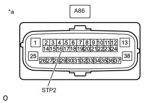
*a Front view of wire harness connector
(to Skid Control ECU (Brake Actuator Assembly))
Turn the ignition switch off.
-
Make sure that there is no looseness at the locking part and the connecting part of the connector.
-
Disconnect the A86 skid control ECU (brake actuator assembly) connector.
-
Measure the voltage according to the value(s) in the table below.
Standard Voltage Tester Connection Condition Specified Condition A86-5 (STP2) - Body ground Stop light switch assembly on (Brake pedal depressed) 8 to 14 V A86-5 (STP2) - Body ground Stop light switch assembly off (Brake pedal released) Below 1.5 V Result Proceed to OK NG
NG
REPAIR OR REPLACE HARNESS OR CONNECTOR (STP2 CIRCUIT)
OK
-
-
PERFORM ACTIVE TEST USING GTS (STOP LIGHT CONTROL RELAY)
-
Reconnect the A86 skid control ECU (brake actuator assembly) connector.
-
Connect the GTS to the DLC3.
-
Turn the ignition switch to ON.
-
Select the Active Test using the GTS.
Chassis > ABS/VSC/TRC > Active TestTester Display Measurement Item Control Range Diagnostic Note Stop Light Relay Stop light control relay Relay ON/OFF Stop lights come on
Chassis > ABS/VSC/TRC > Active TestTester Display Stop Light Relay -
Select the Data List on the GTS.
Chassis > ABS/VSC/TRC > Data ListTester Display Measurement Item Range Normal Condition Diagnostic Note Stop Light Relay Stop light control relay ON or OFF ON: Stop light control relay on
OFF: Stop light control relay off
w/ Downhill assist control or dynamic radar cruise control
Chassis > ABS/VSC/TRC > Data ListTester Display Stop Light Relay -
Check the operating condition of the stop light control relay when operating it using the GTS.
Result Proceed to OK NG
NG
INSPECT STOP LIGHT SWITCH ASSEMBLY Click here
OK
-
-
RECONFIRM DTC
-
Turn the ignition switch off.
-
Clear the DTCs.
Chassis > ABS/VSC/TRC > Clear DTCs -
Turn the ignition switch off.
-
Start the engine.
-
Perform a road test.
-
Check if the same DTC is output.
Chassis > ABS/VSC/TRC > Trouble CodesResult Result Proceed to DTC C1380 is not output. A DTC C1380 is output. B Tech Tips
If troubleshooting has been carried out according to Problem Symptoms Table, refer back to the table and proceed to the next step before replacing parts.
A
USE SIMULATION METHOD TO CHECK Click here
B
REPLACE BRAKE ACTUATOR ASSEMBLY Click here
-
-
INSPECT STOP LIGHT SWITCH ASSEMBLY
-
Turn the ignition switch off.
-
Check the stop light switch assembly.
OK The stop light switch assembly is normal. Result Proceed to OK NG
NG
REPLACE STOP LIGHT SWITCH ASSEMBLY Click here
OK
-
-
CHECK HARNESS AND CONNECTOR (STPO TERMINAL)
-
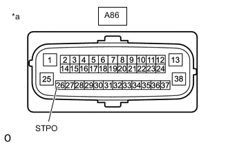
*a Front view of wire harness connector
(to Skid Control ECU (Brake Actuator Assembly))
Make sure that there is no looseness at the locking part and the connecting part of the connector.
-
Disconnect the A86 skid control ECU (brake actuator assembly) connector.
-
Turn the ignition switch to ON.
-
Measure the voltage according to the value(s) in the table below.
Standard Voltage Tester Connection Condition Specified Condition A86-26 (STPO) - Body ground Ignition switch ON 11 to 14 V Tech Tips
If troubleshooting has been carried out according to Problem Symptoms Table, refer back to the table and proceed to the next step before replacing parts.
Result Proceed to OK NG
OK
REPLACE BRAKE ACTUATOR ASSEMBLY Click here
NG
REPAIR OR REPLACE HARNESS OR CONNECTOR (STPO CIRCUIT)
-
-
CHECK HARNESS AND CONNECTOR (STP TERMINAL)
-
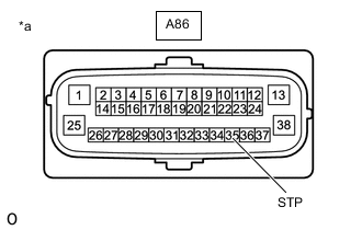
*a Front view of wire harness connector
(to Skid Control ECU (Brake Actuator Assembly))
Turn the ignition switch off.
-
Make sure that there is no looseness at the locking part and the connecting part of the connector.
-
Disconnect the A86 skid control ECU (brake actuator assembly) connector.
-
Measure the voltage according to the value(s) in the table below.
Standard Voltage Tester Connection Condition Specified Condition A86-35 (STP) - Body ground Stop light switch assembly on (Brake pedal depressed) 8 to 14 V A86-35 (STP) - Body ground Stop light switch assembly off (Brake pedal released) Below 1.5 V Tech Tips
If troubleshooting has been carried out according to Problem Symptoms Table, refer back to the table and proceed to the next step before replacing parts.
Result Proceed to OK NG
OK
REPLACE BRAKE ACTUATOR ASSEMBLY Click here
NG
REPAIR OR REPLACE HARNESS OR CONNECTOR (STP CIRCUIT)
-