VEHICLE STABILITY CONTROL SYSTEM, Diagnostic DTC:C1337

| DTC Code | DTC Name |
|---|---|
| C1337 | Diameter of the Tire is not Uniform |
DESCRIPTION
The skid control ECU (brake actuator assembly) measures the speed of each wheel by receiving signals from the speed sensor. These signals are used for recognizing that all 4 wheels are operating properly.
Therefore, all wheel signals must be equal.
| DTC No. | Detection Item | DTC Detection Condition | Trouble Area |
|---|---|---|---|
| C1337 | Diameter of the Tire is not Uniform | The following occurs in 3 consecutive times: At a vehicle speed of 20 km/h (12 mph) or more, there is a 20% difference or greater in the average speed between the front wheels and rear wheels for 20 seconds or more. |
|
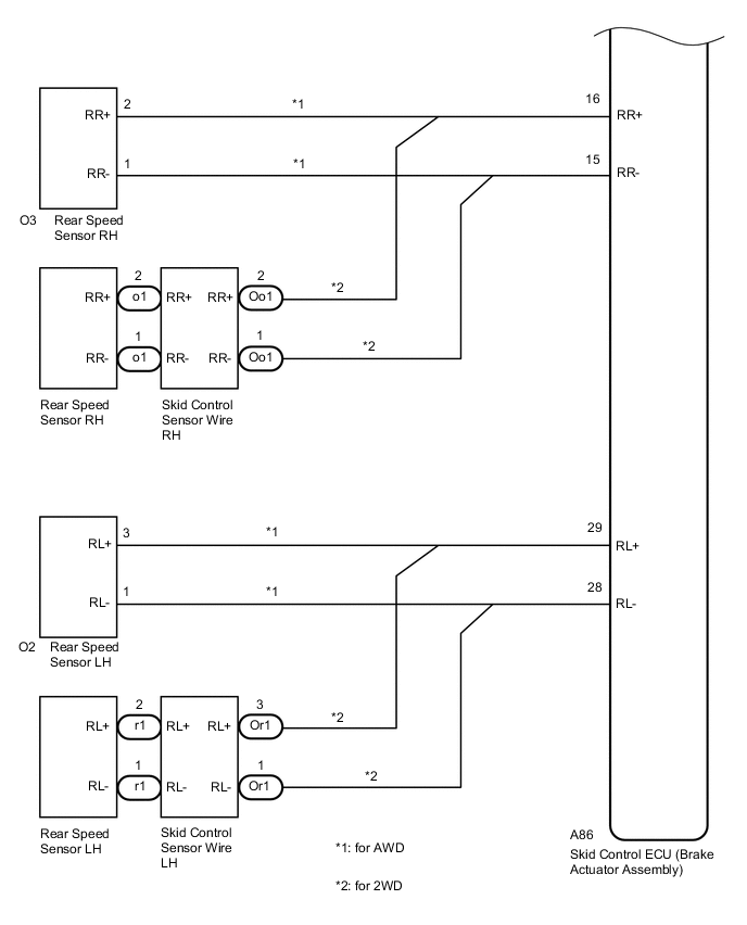
WIRING DIAGRAM
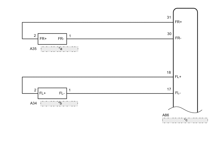
| *a | Front Speed Sensor RH |
| *b | Front Speed Sensor LH |
| *c | Skid Control ECU (Brake Actuator Assembly) |
CAUTION / NOTICE / HINT
Note
When replacing the skid control ECU (brake actuator assembly), perform zero point calibration and store system information.
PROCEDURE
-
CHECK TIRES
-
Check the size and condition of all four wheels.
Tech Tips
The DTC is output when tire deformation or a difference in tire size is detected.
OK The diameter of all four tires and the tire pressure are the same. Result Proceed to OK NG
NG 
REPLACE TIRES SO THAT ALL FOUR TIRES ARE SAME SIZE
OK 
-
-
READ VALUE USING GTS (SPEED SENSOR)
-
Connect the GTS to the DLC3.
-
Start the engine.
-
Select the Data List using the GTS.
Chassis > ABS/VSC/TRC > Data ListTester Display Measurement Item Range Normal Condition Diagnostic Note FR Wheel Speed Front wheel speed sensor RH reading Min.: 0 km/h (0 mph), Max.: 326 km/h (202 mph) Vehicle stopped: 0 km/h (0 mph) When driving at constant speed: No large fluctuations FL Wheel Speed Front wheel speed sensor LH reading Min.: 0 km/h (0 mph), Max.: 326 km/h (202 mph) Vehicle stopped: 0 km/h (0 mph) When driving at constant speed: No large fluctuations RR Wheel Speed Rear wheel speed sensor RH reading Min.: 0 km/h (0 mph), Max.: 326 km/h (202 mph) Vehicle stopped: 0 km/h (0 mph) When driving at constant speed: No large fluctuations RL Wheel Speed Rear wheel speed sensor LH reading Min.: 0 km/h (0 mph), Max.: 326 km/h (202 mph) Vehicle stopped: 0 km/h (0 mph) When driving at constant speed: No large fluctuations
Chassis > ABS/VSC/TRC > Data ListTester Display FR Wheel Speed FL Wheel Speed RR Wheel Speed RL Wheel Speed -
Check the speed value output from the speed sensor displayed on the GTS.
Tech Tips
Factors that affect the indicated vehicle speed include tire size, tire pressure, and tire wear. The speed indicated on the speedometer has an allowable margin of error. This can be tested using a speedometer tester (calibrated chassis dynamometer). For details about testing and the margin of error, see the reference chart.
OK The speed value output from the speed sensor displayed on the GTS is similar to the speed indicated on the speedometer. Result Result Proceed to OK A NG (for front) B NG (for rear 2WD) C NG (for rear AWD) D
B 
CHECK FRONT SPEED SENSOR AND SENSOR ROTOR Click here
C
INSPECT SKID CONTROL SENSOR WIRE Click here
D
CHECK REAR SPEED SENSOR AND SENSOR ROTOR Click here
A
-
-
PERFORM TEST MODE INSPECTION (SIGNAL CHECK)
-
Turn the ignition switch off.
-
Perform the sensor check using the Test Mode procedure.
OK All Test Mode DTCs are not output.
Chassis > ABS/VSC/TRC > UtilityTester Display Signal Check Result Result Proceed to OK A NG (for front) B NG (for rear 2WD) C NG (for rear AWD) D
A
USE SIMULATION METHOD TO CHECK Click here
C
GO TO STEP 12 Click here
D
GO TO STEP 18 Click here
B
-
-
CHECK FRONT SPEED SENSOR AND SENSOR ROTOR
-
Turn the ignition switch off.
-
Remove the front speed sensor and the component with the sensor rotor.
for speed sensor: Click here
for sensor rotor (for 1AR-FE): Click here
for sensor rotor (for 2GR-FKS): Click here
-
Check the speed sensor tip and speed sensor rotor.
OK No scratches, oil, or foreign matter on the sensor tip and rotor. Note
-
If no damage to the speed sensor tip is found during this inspection, do not replace the speed sensor.
If there are any ferrous metal filings stuck to the rotor, this will result in a malfunction, so confirm that the rotor is not contaminated with foreign matter before replacing the sensor.
-
Check the speed sensor signal after cleaning or replacement.
Result Proceed to OK NG -
NG
CLEAN OR REPLACE FRONT SPEED SENSOR OR COMPONENT WITH SENSOR ROTOR
OK
-
-
CHECK HARNESS AND CONNECTOR (BRAKE ACTUATOR ASSEMBLY - FRONT SPEED SENSOR)
-
Make sure that there is no looseness at the locking part and the connecting part of the connector.
-
Disconnect the A86 skid control ECU (brake actuator assembly) connector.
-
Disconnect the A35 or A34 front speed sensor connector.
-
Measure the resistance according to the value(s) in the table below.
Standard Resistance for RH Tester Connection Condition Specified Condition A86-31 (FR+) - A35-2 (FR+) Always Below 1 Ω A86-31 (FR+) or A35-2 (FR+) - Body ground Always 10 kΩ or higher A86-30 (FR-) - A35-1 (FR-) Always Below 1 Ω A86-30 (FR-) or A35-1 (FR-) - Body ground Always 10 kΩ or higher for LH Tester Connection Condition Specified Condition A86-18 (FL+) - A34-2 (FL+) Always Below 1 Ω A86-18 (FL+) or A34-2 (FL+) - Body ground Always 10 kΩ or higher A86-17 (FL-) - A34-1 (FL-) Always Below 1 Ω A86-17 (FL-) or A34-1 (FL-) - Body ground Always 10 kΩ or higher Result Proceed to OK NG
NG
REPAIR OR REPLACE HARNESS OR CONNECTOR
OK
-
-
INSPECT BRAKE ACTUATOR ASSEMBLY (SENSOR INPUT)
-
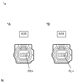
*A RH *B LH *a Front view of wire harness connector
(to Front Speed Sensor)
Reconnect the A86 skid control ECU (brake actuator assembly) connector.
-
Turn the ignition switch to ON.
-
Measure the voltage according to the value(s) in the table below.
Standard Voltage for RH Tester Connection Condition Specified Condition A35-2 (FR+) - Body ground Ignition switch ON 5.7 to 14 V for LH Tester Connection Condition Specified Condition A34-2 (FL+) - Body ground Ignition switch ON 5.7 to 14 V Result Proceed to OK NG
NG
REPLACE BRAKE ACTUATOR ASSEMBLY Click here
OK
-
-
RECONFIRM DTC
-
Turn the ignition switch off.
-
Reconnect the A35 or A34 front speed sensor connector.
-
Clear the DTCs.
Chassis > ABS/VSC/TRC > Clear DTCs -
Turn the ignition switch off.
-
Start the engine.
-
Perform a road test.
-
Check if the same DTC is output.
Chassis > ABS/VSC/TRC > Trouble CodesResult Result Proceed to DTC C1337 is output. A DTC C1337 is not output. B
B
USE SIMULATION METHOD TO CHECK Click here
A
-
-
REPLACE SPEED SENSOR FRONT RH
-
Turn the ignition switch off.
-
Replace the front speed sensor.
Result Proceed to NEXT
NEXT
-
-
RECONFIRM DTC
-
Turn the ignition switch off.
-
Clear the DTCs.
Chassis > ABS/VSC/TRC > Clear DTCs -
Turn the ignition switch off.
-
Start the engine.
-
Perform a road test.
-
Check if the same DTC is output.
Chassis > ABS/VSC/TRC > Trouble CodesResult Result Proceed to DTC C1337 is output. A DTC C1337 is not output. B
B
END
A
-
-
REPLACE FRONT DRIVE SHAFT ASSEMBLY
-
Turn the ignition switch off.
-
Replace the front speed sensor rotor (front drive shaft assembly).
for 1AR-FE: Click here
for 2GR-FKS: Click here
Tech Tips
If the front speed sensor rotor needs to be replaced, replace the front drive shaft assembly.
Result Proceed to NEXT
NEXT
-
-
RECONFIRM DTC
-
Turn the ignition switch off.
-
Clear the DTCs.
Chassis > ABS/VSC/TRC > Clear DTCs -
Turn the ignition switch off.
-
Start the engine.
-
Perform a road test.
-
Check if the same DTC is output.
Chassis > ABS/VSC/TRC > Trouble CodesResult Result Proceed to DTC C1337 is output. A DTC C1337 is not output. B
A
REPLACE BRAKE ACTUATOR ASSEMBLY Click here
B
END
-
-
INSPECT SKID CONTROL SENSOR WIRE
-
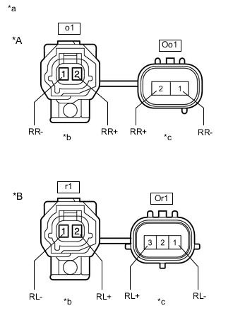
*A RH *B LH *a Front view of Skid Control Sensor Wire *b Front view of wire harness connector
(to Sensor Side Connector)
*c Front view of wire harness connector
(to Vehicle Side Connector)
Turn the ignition switch off.
-
Make sure that there is no looseness at the locking part and the connecting part of the connectors.
-
Remove the skid control sensor wire.
-
Measure the resistance according to the value(s) in the table below.
Standard Resistance for RH Tester Connection Condition Specified Condition o1-2 (RR+) - Oo1-2 (RR+) Always Below 1 Ω o1-2 (RR+) - Oo1-1 (RR-) Always 10 kΩ or higher o1-2 (RR+) or Oo1-2 (RR+) - Body ground Always 10 kΩ or higher o1-1 (RR-) - Oo1-1 (RR-) Always Below 1 Ω o1-1 (RR-) - Oo1-2 (RR+) Always 10 kΩ or higher o1-1 (RR-) or Oo1-1 (RR-) - Body ground Always 10 kΩ or higher for LH Tester Connection Condition Specified Condition r1-2 (RL+) - Or1-3 (RL+) Always Below 1 Ω r1-2 (RL+) - Or1-1 (RL-) Always 10 kΩ or higher r1-2 (RL+) or Or1-3 (RL+) - Body ground Always 10 kΩ or higher r1-1 (RL-) - Or1-1 (RL-) Always Below 1 Ω r1-1 (RL-) - Or1-3 (RL+) Always 10 kΩ or higher r1-1 (RL-) or Or1-1 (RL-) - Body ground Always 10 kΩ or higher Result Proceed to OK NG
NG
REPLACE SKID CONTROL SENSOR WIRE Click here
OK
-
-
CHECK HARNESS AND CONNECTOR (BRAKE ACTUATOR ASSEMBLY - SKID CONTROL SENSOR WIRE)
-
Make sure that there is no looseness at the locking part and the connecting part of the connector.
-
Disconnect the A86 skid control ECU (brake actuator assembly) connector.
-
Measure the resistance according to the value(s) in the table below.
Standard Resistance for RH Tester Connection Condition Specified Condition A86-16 (RR+) - Oo1-2 (RR+) Always Below 1 Ω A86-16 (RR+) or Oo1-2 (RR+) - Body ground Always 10 kΩ or higher A86-15 (RR-) - Oo1-1 (RR-) Always Below 1 Ω A86-15 (RR-) or Oo1-1 (RR-) - Body ground Always 10 kΩ or higher for LH Tester Connection Condition Specified Condition A86-29 (RL+) - Or1-3 (RL+) Always Below 1 Ω A86-29 (RL+) or Or1-3 (RL+) - Body ground Always 10 kΩ or higher A86-28 (RL-) - Or1-1 (RL-) Always Below 1 Ω A86-28 (RL-) or Or1-1 (RL-) - Body ground Always 10 kΩ or higher Result Proceed to OK NG
NG
REPAIR OR REPLACE HARNESS OR CONNECTOR
OK
-
-
INSPECT BRAKE ACTUATOR ASSEMBLY (SENSOR INPUT)
-

*A RH *B LH *a Front view of wire harness connector
(to Skid Control Sensor Wire)
Reconnect the A86 skid control ECU (brake actuator assembly) connector.
-
Turn the ignition switch to ON.
-
Measure the voltage according to the value(s) in the table below.
Standard Voltage for RH Tester Connection Condition Specified Condition Oo1-2 (RR+) - Body ground Ignition switch ON 5.7 to 14 V for LH Tester Connection Condition Specified Condition Or1-3 (RL+) - Body ground Ignition switch ON 5.7 to 14 V Result Proceed to OK NG
NG
REPLACE BRAKE ACTUATOR ASSEMBLY Click here
OK
-
-
RECONFIRM DTC
-
Turn the ignition switch off.
-
Install the skid control sensor wire.
-
Clear the DTCs.
Chassis > ABS/VSC/TRC > Clear DTCs -
Turn the ignition switch off.
-
Start the engine.
-
Perform a road test.
-
Check if the same DTC is output.
Chassis > ABS/VSC/TRC > Trouble CodesResult Result Proceed to DTC C1337 is output. A DTC C1337 is not output. B
B
USE SIMULATION METHOD TO CHECK Click here
A
-
-
REPLACE REAR AXLE HUB AND BEARING ASSEMBLY WITH REAR SPEED SENSOR
-
Turn the ignition switch off.
-
Replace the rear speed sensor rotor (rear axle hub and bearing assembly) with rear speed sensor.
Tech Tips
The rear speed sensor rotor and rear speed sensor are incorporated into the rear axle hub and bearing assembly.
If the rear speed sensor rotor needs to be replaced, replace the rear axle hub and bearing assembly with rear speed sensor.
Result Proceed to NEXT
NEXT
-
-
RECONFIRM DTC
-
Clear the DTCs.
Chassis > ABS/VSC/TRC > Clear DTCs -
Turn the ignition switch off.
-
Start the engine.
-
Perform a road test.
-
Check if the same DTC is output.
Chassis > ABS/VSC/TRC > Trouble CodesResult Result Proceed to DTC C1337 is output. A DTC C1337 is not output. B
A
REPLACE BRAKE ACTUATOR ASSEMBLY Click here
B
END
-
-
CHECK REAR SPEED SENSOR AND SENSOR ROTOR
-
Turn the ignition switch off.
-
Remove the rear speed sensor and the component with the sensor rotor.
for speed sensor: Click here
for sensor rotor: Click here
-
Check the speed sensor tip and speed sensor rotor.
OK No scratches, oil, or foreign matter on the sensor tip and rotor. Note
-
If no damage to the speed sensor tip is found during this inspection, do not replace the speed sensor.
If there are any ferrous metal filings stuck to the rotor, this will result in a malfunction, so confirm that the rotor is not contaminated with foreign matter before replacing the sensor.
-
Check the speed sensor signal after cleaning or replacement.
Result Proceed to OK NG -
NG
CLEAN OR REPLACE REAR SPEED SENSOR OR COMPONENT WITH SENSOR ROTOR
OK
-
-
CHECK HARNESS AND CONNECTOR (BRAKE ACTUATOR ASSEMBLY - REAR SPEED SENSOR)
-
Install the rear speed sensor and the component with the sensor rotor.
-
Make sure that there is no looseness at the locking part and the connecting part of the connectors.
-
Disconnect the A86 skid control ECU (brake actuator assembly) connector.
-
Disconnect the O3 or O2 rear speed sensor connector.
-
Measure the resistance according to the value(s) in the table below.
Standard Resistance for RH Tester Connection Condition Specified Condition A86-16 (RR+) - O3-2 (RR+) Always Below 1 Ω A86-16 (RR+) or O3-2 (RR+) - Body ground Always 10 kΩ or higher A86-15 (RR-) - O3-1 (RR-) Always Below 1 Ω A86-15 (RR-) or O3-1 (RR-) - Body ground Always 10 kΩ or higher for LH Tester Connection Condition Specified Condition A86-29 (RL+) - O2-3 (RL+) Always Below 1 Ω A86-29 (RL+) or O2-3 (RL+) - Body ground Always 10 kΩ or higher A86-28 (RL-) - O2-1 (RL-) Always Below 1 Ω A86-28 (RL-) or O2-1 (RL-) - Body ground Always 10 kΩ or higher Result Proceed to OK NG
NG
REPAIR OR REPLACE HARNESS OR CONNECTOR
OK
-
-
INSPECT BRAKE ACTUATOR ASSEMBLY (SENSOR INPUT)
-
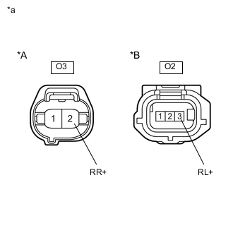
*A RH *B LH *a Front view of wire harness connector
(to Rear Speed Sensor)
Reconnect the A86 skid control ECU (brake actuator assembly) connector.
-
Turn the ignition switch to ON.
-
Measure the voltage according to the value(s) in the table below.
Standard Voltage for RH Tester Connection Condition Specified Condition O3-2 (RR+) - Body ground Ignition switch ON 5.7 to 14 V for LH Tester Connection Condition Specified Condition O2-3 (RL+) - Body ground Ignition switch ON 5.7 to 14 V Result Proceed to OK NG
NG
REPLACE BRAKE ACTUATOR ASSEMBLY Click here
OK
-
-
RECONFIRM DTC
-
Turn the ignition switch off.
-
Reconnect the O3 or O2 rear speed sensor connector.
-
Clear the DTCs.
Chassis > ABS/VSC/TRC > Clear DTCs -
Turn the ignition switch off.
-
Start the engine.
-
Perform a road test.
-
Check if the same DTC is output.
Chassis > ABS/VSC/TRC > Trouble CodesResult Result Proceed to DTC C1337 is output. A DTC C1337 is not output. B
B
USE SIMULATION METHOD TO CHECK Click here
A
-
-
REPLACE REAR SPEED SENSOR
-
Turn the ignition switch off.
-
Replace the rear speed sensor.
Result Proceed to NEXT
NEXT
-
-
RECONFIRM DTC
-
Clear the DTCs.
Chassis > ABS/VSC/TRC > Clear DTCs -
Turn the ignition switch off.
-
Start the engine.
-
Perform a road test.
-
Check if the same DTC is output.
Chassis > ABS/VSC/TRC > Trouble CodesResult Result Proceed to DTC C1337 is output. A DTC C1337 is not output. B
B
END
A
-
-
REPLACE REAR AXLE HUB AND BEARING ASSEMBLY
-
Turn the ignition switch off.
-
Replace the rear speed sensor rotor (rear axle hub and bearing assembly).
Tech Tips
The rear speed sensor rotor is incorporated into the rear axle hub and bearing assembly.
If the rear speed sensor rotor needs to be replaced, replace the rear axle hub and bearing assembly.
Result Proceed to NEXT
NEXT
-
-
RECONFIRM DTC
-
Clear the DTCs.
Chassis > ABS/VSC/TRC > Clear DTCs -
Turn the ignition switch off.
-
Start the engine.
-
Perform a road test.
-
Check if the same DTC is output.
Chassis > ABS/VSC/TRC > Trouble CodesResult Result Proceed to DTC C1337 is output. A DTC C1337 is not output. B
A
REPLACE BRAKE ACTUATOR ASSEMBLY Click here
B
END
-