REAR SUSPENSION MEMBER(for 2WD) INSTALLATION

PROCEDURE
-
INSTALL HOLE PLUG
-
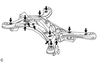
Install the 13 hole plugs to the rear suspension member sub-assembly as shown in the illustration.
Tech Tips
The upper and lower hole plug shapes are different.
-
-
INSTALL REAR SUSPENSION MEMBER FRONT BODY MOUNTING CUSHION (for LH Side)
-
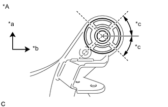
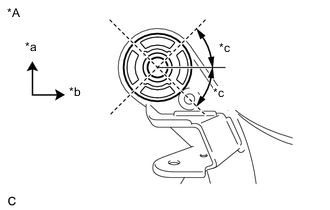
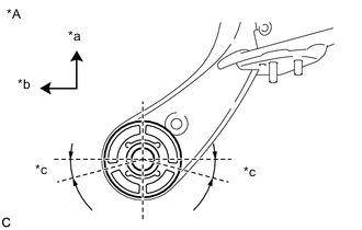
*A View from Underneath *a Front of the Vehicle *b Left Side of the Vehicle *c 45° Temporarily install the rear suspension member front body mounting cushion while confirming the installation direction.
-
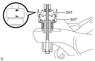
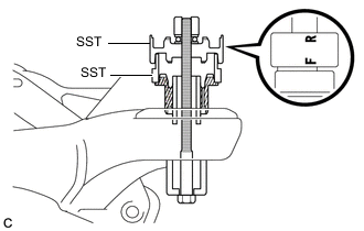
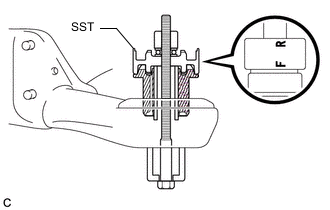
Install SST as shown in the illustration.
- SST
- 09527-17011
- 09830-10010 ( 09830-01010, 09830-01020, 09830-01030, 09830-01060 )
Note
Apply grease to the threads and tip of the SST center bolt before use.
Tech Tips
Use SST with the "F" mark facing the rear suspension member front body mounting cushion.
-
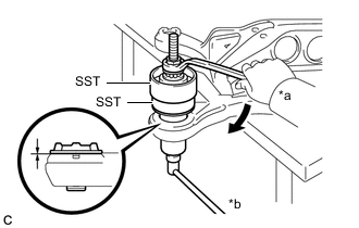
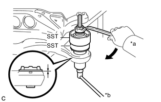
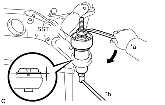
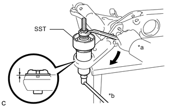
*a Turn *b Hold Using SST, install the rear suspension member front body mounting cushion until there is no clearance between the rear suspension member sub-assembly and rear suspension member front body mounting cushion.
- SST
- 09527-17011
- 09830-10010 ( 09830-01010, 09830-01020, 09830-01030, 09830-01060 )
Note
If the rear suspension member sub-assembly is scratched, apply paint to the scratched areas of the rear suspension member sub-assembly.
-
Remove SST from the rear suspension member sub-assembly.
-
-
INSTALL REAR SUSPENSION MEMBER FRONT BODY MOUNTING CUSHION (for RH Side)
-
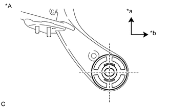
*A View from Underneath *a Front of the Vehicle *b Left Side of the Vehicle *c 45° Temporarily install the rear suspension member front body mounting cushion while confirming the installation direction.
-
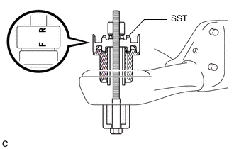
Install SST as shown in the illustration.
- SST
- 09527-17011
- 09830-10010 ( 09830-01010, 09830-01020, 09830-01030, 09830-01060 )
Note
Apply grease to the threads and tip of the SST center bolt before use.
Tech Tips
Use SST with the "F" mark facing the rear suspension member front body mounting cushion.
-
*a Turn *b Hold Using SST, install the rear suspension member front body mounting cushion until there is no clearance between the rear suspension member sub-assembly and rear suspension member front body mounting cushion.
- SST
- 09527-17011
- 09830-10010 ( 09830-01010, 09830-01020, 09830-01030, 09830-01060 )
Note
If the rear suspension member sub-assembly is scratched, apply paint to the scratched areas of the rear suspension member sub-assembly.
-
Remove SST from the rear suspension member sub-assembly.
-
-
INSTALL REAR SUSPENSION MEMBER REAR BODY MOUNTING CUSHION LH
-
*A View from Underneath *a Front of the Vehicle *b Left Side of the Vehicle Temporarily install the rear suspension member rear body mounting cushion LH while confirming the installation direction.
-
Install SST as shown in the illustration.
- SST
- 09830-10010 ( 09830-01010, 09830-01020, 09830-01030, 09830-01060 )
Note
Apply grease to the threads and tip of the SST center bolt before use.
Tech Tips
Use SST with the "F" mark facing the rear suspension member rear body mounting cushion LH.
-
*a Turn *b Hold Using SST, install the rear suspension member rear body mounting cushion LH until there is no clearance between the rear suspension member sub-assembly and rear suspension member rear body mounting cushion LH.
- SST
- 09830-10010 ( 09830-01010, 09830-01020, 09830-01030, 09830-01060 )
Note
If the rear suspension member sub-assembly is scratched, apply paint to the scratched areas of the rear suspension member sub-assembly.
-
Remove SST from the rear suspension member sub-assembly.
-
-
INSTALL REAR SUSPENSION MEMBER REAR BODY MOUNTING CUSHION RH
-
*A View from Underneath *a Front of the Vehicle *b Right Side of the Vehicle *c 15° Temporarily install the rear suspension member rear body mounting cushion RH while confirming the installation direction.
-
Install SST as shown in the illustration.
- SST
- 09830-10010 ( 09830-01010, 09830-01020, 09830-01030, 09830-01060 )
Note
Apply grease to the threads and tip of the SST center bolt before use.
Tech Tips
Use SST with the "F" mark facing the rear suspension member rear body mounting cushion RH.
-
*a Turn *b Hold Using SST, install the rear suspension member rear body mounting cushion RH until there is no clearance between the rear suspension member sub-assembly and rear suspension member rear body mounting cushion RH.
- SST
- 09830-10010 ( 09830-01010, 09830-01020, 09830-01030, 09830-01060 )
Note
If the rear suspension member sub-assembly is scratched, apply paint to the scratched areas of the rear suspension member sub-assembly.
-
Remove SST from the rear suspension member sub-assembly.
-
-
INSTALL REAR UPPER CONTROL ARM ASSEMBLY LH
-
INSTALL REAR UPPER CONTROL ARM ASSEMBLY RH
Tech Tips
Perform the same procedure as for the LH side.
-
INSTALL SKID CONTROL SENSOR WIRE LH
-
Install the skid control sensor wire LH with the 2 bolts and nut.
- Torque:
- Bolt
- 8.0 N*m { 82 kgf*cm, 71 in.*lbf }
- Nut
- 9.0 N*m { 92 kgf*cm, 80 in.*lbf }
-
-
INSTALL SKID CONTROL SENSOR WIRE RH
Tech Tips
Perform the same procedure as for the LH side.
-
INSTALL REAR SUSPENSION MEMBER UPPER STOPPER
-
Install the 2 rear suspension member upper stoppers to the rear suspension member sub-assembly.
Note
Be sure to install the rear suspension member upper stoppers in the correct direction shown in the illustration.
-
-
INSTALL REAR SUSPENSION MEMBER REAR UPPER STOPPER
-
Install the 2 rear suspension member rear upper stoppers to the rear suspension member sub-assembly.
-
-
INSTALL REAR SUSPENSION MEMBER SUB-ASSEMBLY
-
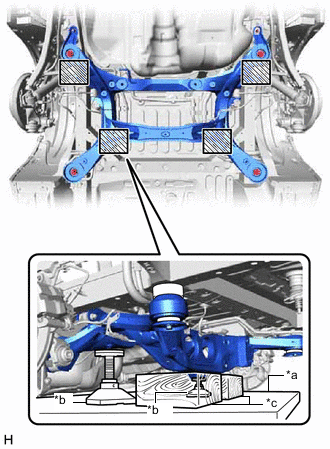
*a Engine Lifter *b Attachment *c Wooden Block 
Attachment placement location Support the rear suspension member sub-assembly with an engine lifter using 2 wooden blocks and 2 attachments or equivalent tools as shown in the illustration.
CAUTION:
Make sure to secure the rear suspension member sub-assembly to prevent it from dropping.
Note
-
Use the attachments to keep the rear suspension member sub-assembly level.
-
The rear suspension member sub-assembly is a heavy component. Make sure that it is supported securely.
-
Keep supporting the rear suspension member sub-assembly until the installation has been completed.
-
-
Temporarily install the rear No. 1 suspension arm assembly LH.
-
*a Wooden Block *b Jack *c Opening *d Spacer 
Front of the Vehicle Support the rear axle assembly LH with a jack using a wooden block as shown in the illustration.
CAUTION:
Do not jack up the rear axle assembly LH too high as the vehicle may fall.
Note
When jacking up the rear axle assembly LH, be sure to jack it up slowly.
-
Temporarily install the rear No. 1 suspension arm assembly LH to the rear axle carrier sub-assembly LH with the spacer and nut (A).
Note
-
Install the rear No. 1 suspension arm assembly with its opening facing downward.
-
Fully tighten the nut (A) after stabilizing the suspension.
-
Be sure to install the rear No. 1 suspension arm assembly with the spacer facing in the correct direction as shown in the illustration.
-
-
Temporarily install the rear No. 1 suspension arm assembly LH to the rear suspension member sub-assembly with the bolt (B) and nut.
Note
-
Insert the bolt with the threaded end facing the rear of the vehicle.
-
Because the nut has its own stopper, do not turn the nut. Tighten the bolt with the nut secured.
-
Fully tighten the bolt (B) after stabilizing the suspension.
-
-
-
Slowly lower the rear axle assembly LH.
-
Temporarily install the rear No. 1 suspension arm assembly RH.
Tech Tips
Perform the same procedure as for the LH side.
-
Install the rear suspension member sub-assembly with the 2 rear lower suspension braces, rear lower suspension member stopper LH and rear lower suspension member stopper RH, with the 4 bolts and 2 nuts.
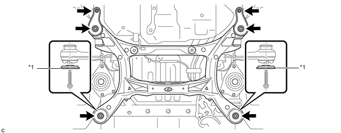
*1 Rear Lower Suspension Brace - - - Torque:
- Bolt
- 158 N*m { 1611 kgf*cm, 117 ft.*lbf }
- Nut
- 32 N*m { 326 kgf*cm, 24 ft.*lbf }
Note
Be sure to install the rear suspension member sub-assembly with the rear lower suspension braces facing in the correct direction as shown in the illustration.
-
Lower the engine lifter.
-
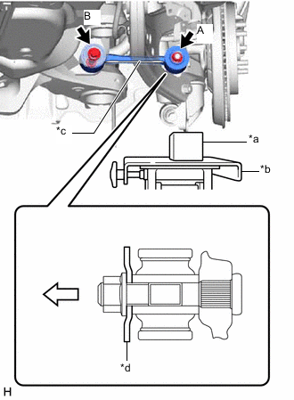
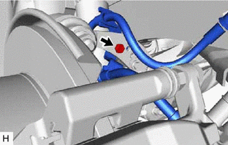
Connect the rear upper control arm assembly LH.
-
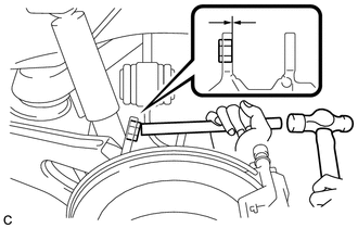
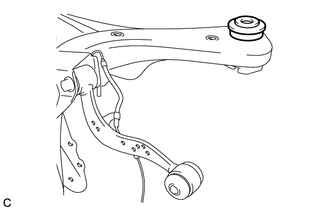
Using a brass bar and a hammer, push out the bushing until it is positioned as shown in the illustration.
Tech Tips
Pushing out the bushing makes it easier to connect the rear upper control arm assembly LH.
-
*a Wooden Block *b Jack Support the rear axle assembly LH with a jack using a wooden block as shown in the illustration.
CAUTION:
Do not jack up the rear axle assembly LH too high as the vehicle may fall.
Note
When jacking up the rear axle assembly LH, be sure to jack it up slowly.
-
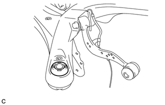
Connect the rear upper control arm assembly LH to the rear axle carrier sub-assembly LH with the bolt and nut.
- Torque:
- 145 N*m { 1479 kgf*cm, 107 ft.*lbf }
Note
-
Insert the bolt with the threaded end facing the rear of the vehicle.
-
Because the nut has its own stopper, do not turn the nut. Tighten the bolt with the nut secured.
-
Slowly lower the rear axle assembly LH.
-
-
Connect the rear upper control arm assembly RH.
Tech Tips
Perform the same procedure as for the LH side.
-
-
INSTALL FRAME WIRE
-
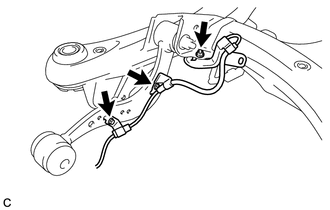
Install the frame wire to the rear suspension member sub-assembly with the bolt, each clamp and each connector as shown in the illustration.
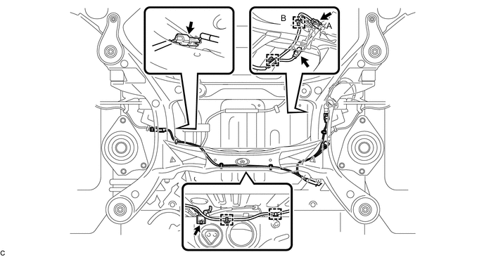
- Torque:
- 5.0 N*m { 51 kgf*cm, 44 in.*lbf }
Note
Do not twist the frame wire when installing it.
Tech Tips
The connector (A) and clamp (B) are only on vehicles with the LED headlight system.
-
-
TEMPORARILY INSTALL REAR NO. 2 SUSPENSION ARM ASSEMBLY LH
-
TEMPORARILY INSTALL REAR NO. 2 SUSPENSION ARM ASSEMBLY RH
Tech Tips
Perform the same procedure as for the LH side.
-
INSTALL REAR STABILIZER BAR
-
INSTALL REAR STABILIZER LINK SUB-ASSEMBLY LH
-
INSTALL REAR STABILIZER LINK SUB-ASSEMBLY RH
Tech Tips
Perform the same procedure as for the LH side.
-
INSTALL SKID CONTROL SENSOR WIRE LH
-
INSTALL SKID CONTROL SENSOR WIRE RH
Tech Tips
Perform the same procedure as for the LH side.
-
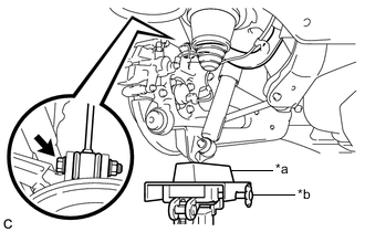
INSTALL REAR FLEXIBLE HOSE LH
-
Install the rear flexible hose LH to the rear upper control arm assembly LH with the bolt.
- Torque:
- 18.8 N*m { 192 kgf*cm, 14 ft.*lbf }
Note
-
Do not twist the rear flexible hose LH when installing it.
-
Do not damage the rear flexible hose when installing it.
-
If the rear flexible hose LH is damaged, replace it with a new one.
-
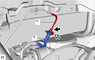
*1 Rear No. 4 Brake Tube *2 Rear Flexible Hose LH Clip Install the rear flexible hose with a new clip.
Note
Install the clip as far as it will go.
-
Using a union nut wrench, connect the rear flexible hose LH to the rear No. 4 brake tube while holding the rear flexible hose LH with a wrench.
- Torque:
- 15.2 N*m { 155 kgf*cm, 11 ft.*lbf }
Note
-
Do not kink or damage the brake line.
-
Do not allow any foreign matter such as dirt or dust to enter the brake line from the connecting parts.
-
Use the formula to calculate special torque values for situations where the union nut wrench is combined with a torque wrench.
-
-
INSTALL REAR FLEXIBLE HOSE RH
Tech Tips
Perform the same procedure as for the LH side.
-
STABILIZE SUSPENSION
-
INSTALL REAR NO. 1 SUSPENSION ARM ASSEMBLY LH
-
INSTALL REAR NO. 1 SUSPENSION ARM ASSEMBLY RH
Tech Tips
Perform the same procedure as for the LH side.
-
INSTALL REAR SUSPENSION ARM COVER LH
-
INSTALL REAR SUSPENSION ARM COVER RH
Tech Tips
Perform the same procedure as for the LH side.
-
INSTALL REAR HEIGHT CONTROL SENSOR SUB-ASSEMBLY (w/ Height Control Sensor)
-
INSTALL TAIL EXHAUST PIPE ASSEMBLY
for 1AR-FE: Click here
for 2GR-FKS: Click here
-
BLEED BRAKE LINE
-
INSTALL REAR WHEEL
- Torque:
- 103 N*m { 1050 kgf*cm, 76 ft.*lbf }
-
INSTALL REAR NO. 2 SUSPENSION ARM ASSEMBLY LH
-
INSTALL REAR NO. 2 SUSPENSION ARM ASSEMBLY RH
Tech Tips
Perform the same procedure as for the LH side.
-
INSPECT AND ADJUST REAR WHEEL ALIGNMENT
-
CHECK FOR SPEED SENSOR SIGNAL