REAR SUSPENSION MEMBER(for 2WD) REMOVAL

PROCEDURE
-
REMOVE REAR WHEEL
-
DRAIN BRAKE FLUID
Note
If brake fluid leaks onto any painted surface, immediately wash it off.
-
REMOVE TAIL EXHAUST PIPE ASSEMBLY
for 1AR-FE: Click here
for 2GR-FE: Click here
-
REMOVE REAR HEIGHT CONTROL SENSOR SUB-ASSEMBLY (w/ Height Control Sensor)
-
SEPARATE REAR FLEXIBLE HOSE LH
-
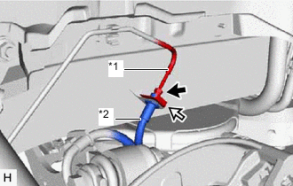
*1 Rear No. 4 Brake Tube *2 Rear Flexible Hose LH 
Clip Using a union nut wrench, separate the rear flexible hose LH from the rear No. 4 brake tube while holding the rear flexible hose LH with a wrench.
Note
-
Do not kink or damage the brake line.
-
Do not allow any foreign matter such as dirt or dust to enter the brake line from the connecting parts.
-
-
Remove the clip and separate the rear flexible hose LH.
-
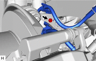
Remove the bolt and separate the rear flexible hose LH from the rear upper control arm assembly LH.
-
-
SEPARATE REAR FLEXIBLE HOSE RH
Tech Tips
Perform the same procedure as for the LH side.
-
REMOVE REAR SUSPENSION ARM COVER LH
-
REMOVE REAR SUSPENSION ARM COVER RH
Tech Tips
Perform the same procedure as for the LH side.
-
SEPARATE SKID CONTROL SENSOR WIRE LH
-
SEPARATE SKID CONTROL SENSOR WIRE RH
Tech Tips
Perform the same procedure as for the LH side.
-
REMOVE REAR STABILIZER LINK SUB-ASSEMBLY LH
-
REMOVE REAR STABILIZER LINK SUB-ASSEMBLY RH
Tech Tips
Perform the same procedure as for the LH side.
-
REMOVE REAR STABILIZER BAR
-
REMOVE REAR NO. 2 SUSPENSION ARM ASSEMBLY LH
-
REMOVE REAR NO. 2 SUSPENSION ARM ASSEMBLY RH
Tech Tips
Perform the same procedure as for the LH side.
-
SEPARATE FRAME WIRE
-
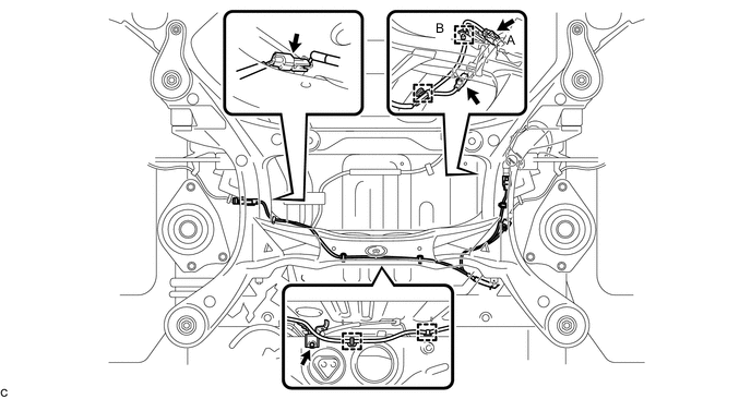
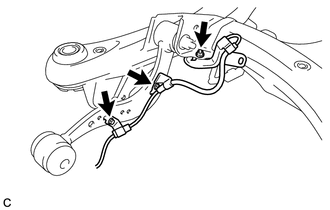
Remove the bolt and disconnect each connector, and then disengage each clamp to separate the frame wire from the rear suspension member sub-assembly as shown in the illustration.
Tech Tips
The connector (A) and the clamp (B) are only on vehicles with the LED headlight system.
-
-
REMOVE REAR SUSPENSION MEMBER SUB-ASSEMBLY
-
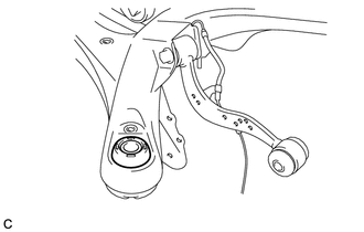
Separate the rear upper control arm assembly LH.
-
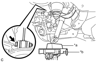
*a Wooden Block *b Jack Support the rear axle assembly LH with a jack using a wooden block as shown in the illustration.
CAUTION:
Do not jack up the rear axle assembly LH too high as the vehicle may fall.
Note
When jacking up the rear axle assembly LH, be sure to jack it up slowly.
-
Remove the bolt and nut, and separate the rear upper control arm assembly LH from the rear axle carrier sub-assembly LH.
Note
Because the nut has its own stopper, do not turn the nut. Loosen the bolt with the nut secured.
-
Slowly lower the rear axle assembly LH.
-
-
Separate the rear upper control arm assembly RH.
Tech Tips
Perform the same procedure as for the LH side.
-
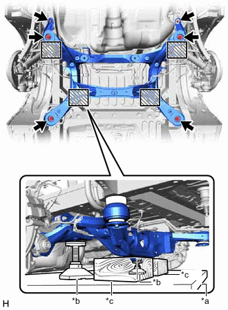
*a Engine Lifter *b Attachment *c Wooden Block 
Attachment placement location Support the rear suspension member sub-assembly with an engine lifter using 2 wooden blocks and 2 attachments or equivalent tools as shown in the illustration.
CAUTION:
Make sure to secure the rear suspension member sub-assembly to prevent it from dropping.
Note
-
Use the attachments to keep the rear suspension member sub-assembly level.
-
The rear suspension member sub-assembly is a heavy component. Make sure that it is supported securely.
-
-
Remove the 4 bolts, 2 nuts, 2 rear lower suspension braces, rear lower suspension member stopper LH and rear lower suspension member stopper RH.
-
Remove the rear No. 1 suspension arm assembly LH.
-
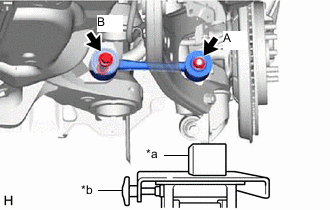
*a Wooden Block *b Jack Support the rear axle assembly LH with a jack using a wooden block as shown in the illustration.
CAUTION:
Do not jack up the rear axle assembly LH too high as the vehicle may fall.
Note
When jacking up the rear axle assembly LH, be sure to jack it up slowly.
-
Remove the nut (A) and the spacer.
-
Remove the bolt (B), nut and rear No. 1 suspension arm assembly LH.
Note
Because the nut has its own stopper, do not turn the nut. Loosen the bolt with the nut secured.
-
Slowly lower the rear axle assembly LH.
-
-
Remove the rear No. 1 suspension arm assembly RH.
Tech Tips
Perform the same procedure as for the LH side.
-
Slowly lower the rear suspension member sub-assembly.
Note
When lowering the rear suspension member sub-assembly, be careful not to damage the vehicle body or other components installed on the vehicle.
-
-
REMOVE REAR SUSPENSION MEMBER UPPER STOPPER
-
Remove the 2 rear suspension member upper stoppers from the rear suspension member sub-assembly.
-
-
REMOVE REAR SUSPENSION MEMBER REAR UPPER STOPPER
-
Remove the 2 rear suspension member rear upper stoppers from the rear suspension member sub-assembly.
-
-
REMOVE SKID CONTROL SENSOR WIRE LH
-
Remove the 2 bolts, nut and skid control sensor wire LH from the rear suspension member sub-assembly.
-
-
REMOVE SKID CONTROL SENSOR WIRE RH
Tech Tips
Perform the same procedure as for the LH side.
-
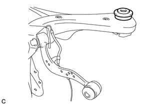
REMOVE REAR UPPER CONTROL ARM ASSEMBLY LH
-
REMOVE REAR UPPER CONTROL ARM ASSEMBLY RH
Tech Tips
Perform the same procedure as for the LH side.
-
REMOVE REAR SUSPENSION MEMBER FRONT BODY MOUNTING CUSHION (for LH Side)
-
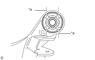
*a Bend Portion Using a chisel and hammer, bend the 2 portions of the rear suspension member front body mounting cushion rib.
Note
Make sure to bend the 2 portions of the cushion rib until the claws of SST can fit securely.
-
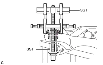
Install SST as shown in the illustration.
- SST
- 09830-10010 ( 09830-01010, 09830-01040, 09830-01050 )
- 09950-40011 ( 09951-04020, 09952-04010, 09954-04010, 09955-04051, 09958-04011 )
Note
Apply grease to the threads and tip of the SST center bolt before use.
-
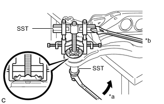
*a Turn *b Hold Using SST, remove the rear suspension member front body mounting cushion while applying grease into the clearance between the rear suspension member front body mounting cushion and the rear suspension member sub-assembly.
- SST
- 09830-10010 ( 09830-01010, 09830-01040, 09830-01050 )
- 09950-40011 ( 09951-04020, 09952-04010, 09954-04010, 09955-04051, 09958-04011 )
Note
-
Set the claws of SST onto the rear suspension member sub-assembly securely as shown in the illustration.
-
Be careful as the rear suspension member front body mounting cushion may fly out.
-
The rear suspension member front body mounting cushion cannot be reused.
-
Remove SST and the rear suspension member front body mounting cushion (LH Side) from the rear suspension member sub-assembly.
-
-
REMOVE REAR SUSPENSION MEMBER FRONT BODY MOUNTING CUSHION (for RH Side)
Tech Tips
Perform the same procedure as for the LH side.
-
REMOVE REAR SUSPENSION MEMBER REAR BODY MOUNTING CUSHION LH
-
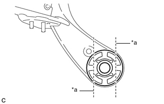
*a Bend Portion Using a chisel and hammer, bend the 2 portions of the rear suspension member rear body mounting cushion LH rib.
Note
Make sure to bend the 2 portions of the cushion rib until the claws of SST can fit securely.
-
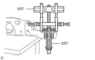
Install SST as shown in the illustration.
- SST
- 09830-10010 ( 09830-01010, 09830-01040, 09830-01050 )
- 09950-40011 ( 09951-04020, 09952-04010, 09954-04010, 09955-04051, 09958-04011 )
Note
Apply grease to the threads and tip of the SST center bolt before use.
-
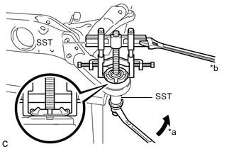
*a Turn *b Hold Using SST, remove the rear suspension member rear body mounting cushion LH while applying grease into the clearance between the rear suspension member rear body mounting cushion LH and the rear suspension member sub-assembly.
- SST
- 09830-10010 ( 09830-01010, 09830-01040, 09830-01050 )
- 09950-40011 ( 09951-04020, 09952-04010, 09954-04010, 09955-04051, 09958-04011 )
Note
-
Set the claws of SST onto the rear suspension member sub-assembly securely as shown in the illustration.
-
Be careful as the rear suspension member rear body mounting cushion LH may fly out.
-
The rear suspension member rear body mounting cushion LH cannot be reused.
-
Remove SST and the rear suspension member rear body mounting cushion LH from the rear suspension member sub-assembly.
-
-
REMOVE REAR SUSPENSION MEMBER REAR BODY MOUNTING CUSHION RH
Tech Tips
Perform the same procedure as for the LH side.
-
REMOVE HOLE PLUG
-
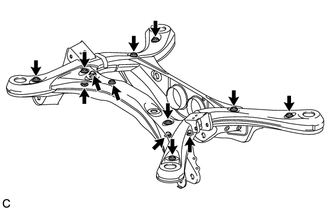
Remove the 13 hole plugs from the rear suspension member sub-assembly as shown in the illustration.
-