REAR LOWER ARM INSTALLATION
CAUTION / NOTICE / HINT
Tech Tips
-
Use the same procedure for the RH side and LH side.
-
The procedure listed below is for the LH side.
PROCEDURE
-
TEMPORARILY INSTALL REAR NO. 1 SUSPENSION ARM ASSEMBLY
-
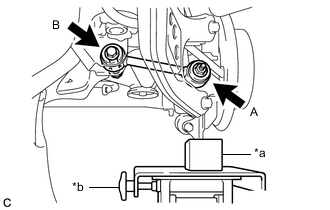
*a Wooden Block *b Jack Temporarily install the rear No. 1 suspension arm assembly to the rear axle carrier sub-assembly with the spacer and nut (A).
Note
Fully tighten the nut (A) after stabilizing the suspension.
-
Temporarily install the rear No. 1 suspension arm assembly to the rear suspension member sub-assembly with the bolt (B) and nut.
Note
-
Insert the bolt with the threaded end facing the rear of the vehicle.
-
Because the nut has its own stopper, do not turn the nut. Tighten the bolt with the nut secured.
-
Fully tighten the bolt (B) after stabilizing the suspension.
-
-
Slowly lower the rear axle assembly.
-
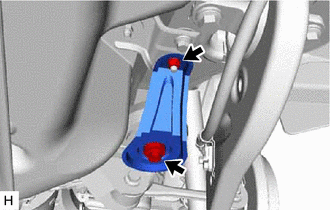
Install the rear lower suspension member stopper with the bolt and nut.
- Torque:
- Bolt
- 158 N*m { 1611 kgf*cm, 117 ft.*lbf }
- Nut
- 32 N*m { 326 kgf*cm, 24 ft.*lbf }
-
Slowly lower the jack.
-
-
TEMPORARILY INSTALL REAR NO. 2 SUSPENSION ARM ASSEMBLY
-
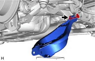
Temporarily install the rear No. 2 suspension arm assembly to the rear suspension member sub-assembly with the No. 2 adjust cam, toe adjust cam sub-assembly and the nut.
Note
-
Insert the toe adjust cam sub-assembly with the threaded end facing the front of the vehicle.
-
When tightening the nut, keep the toe adjust cam sub-assembly from rotating.
-
-
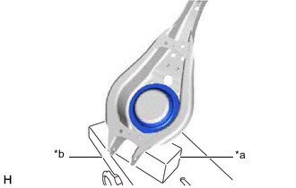
*a Wooden Block *b Jack Support the rear No. 2 suspension arm assembly using a jack and wooden block.
-
Install the rear lower coil spring insulator to the rear No. 2 suspension arm assembly.
-
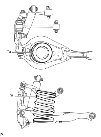
*a Identification Mark Set the rear coil spring to the rear No. 2 suspension arm assembly.
Note
Set the rear coil spring so that the identification mark is positioned as shown in the illustration.
-
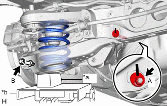
*a Wooden Block *b Jack Using a jack and wooden block, slowly jack up the rear No. 2 suspension arm assembly and then temporarily install the rear No. 2 suspension arm assembly to the rear axle assembly with the bolt (B) and nut.
- Torque:
- 100 N*m { 1020 kgf*cm, 74 ft.*lbf }
CAUTION:
Do not jack up the rear No. 2 suspension arm assembly too high as the vehicle may fall.
Note
-
Because the nut has its own stopper, do not turn the nut. Tighten the bolt with the nut secured.
-
When jacking up the rear No. 2 suspension arm assembly, be sure to jack it up slowly.
-
Insert the bolt with the threaded end facing the front of the vehicle.
-
Fully tighten the nut (A) after stabilizing the suspension.
-
-
INSTALL REAR STABILIZER LINK SUB-ASSEMBLY
-
STABILIZE SUSPENSION
-
INSTALL REAR NO. 1 SUSPENSION ARM ASSEMBLY
-
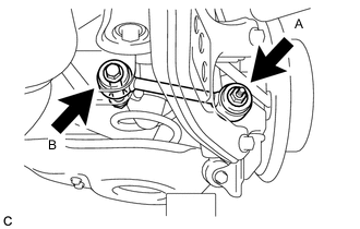
Using a ball joint lock nut wrench, install the rear No. 1 suspension arm assembly with the bolt (B).
- Torque:
- 150 N*m { 1530 kgf*cm, 111 ft.*lbf }
Note
-
Because the nut has its own stopper, do not turn the nut. Tighten the bolt (B) with the nut secured.
-
Use the formula to calculate special torque values for situations where the union nut wrench is combined with a torque wrench.
-
Install the rear No. 1 suspension arm assembly with the nut (A).
- Torque:
- 145 N*m { 1479 kgf*cm, 107 ft.*lbf }
-
-
INSTALL REAR SUSPENSION ARM COVER
-
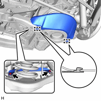
Engage the 2 guides.
-
Install the rear suspension arm cover with the 2 bolts.
- Torque:
- 12 N*m { 122 kgf*cm, 9 ft.*lbf }
-
-
INSTALL REAR WHEEL
- Torque:
- 103 N*m { 1050 kgf*cm, 76 ft.*lbf }
-
INSTALL REAR NO. 2 SUSPENSION ARM ASSEMBLY
-
Lower the vehicle to the ground.
-
Bounce the vehicle up and down at the corners to stabilize the rear suspension.
-
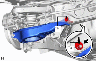
*a Matchmark Install the rear No. 2 suspension arm assembly with the nut.
- Torque:
- 100 N*m { 1020 kgf*cm, 74 ft.*lbf }
Note
-
Align the matchmarks on the toe adjust cam sub-assembly, No. 2 adjust cam and rear suspension member sub-assembly.
-
Hold the toe adjust cam sub-assembly while rotating the nut.
-
Tighten the nut while the vehicle is unloaded.
-
-
INSPECT AND ADJUST REAR WHEEL ALIGNMENT