REAR LOWER ARM REMOVAL
CAUTION / NOTICE / HINT
Tech Tips
-
Use the same procedure for the RH side and LH side.
-
The procedure listed below is for the LH side.
PROCEDURE
-
REMOVE REAR WHEEL
-
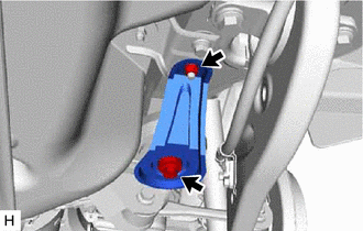
REMOVE REAR SUSPENSION ARM COVER
-
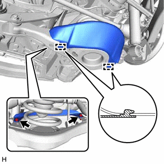
Remove the 2 bolts.
-
Disengage the 2 guides and remove the rear suspension arm cover from the rear No. 2 suspension arm assembly.
-
-
REMOVE REAR STABILIZER LINK SUB-ASSEMBLY
-
REMOVE REAR NO. 2 SUSPENSION ARM ASSEMBLY
-
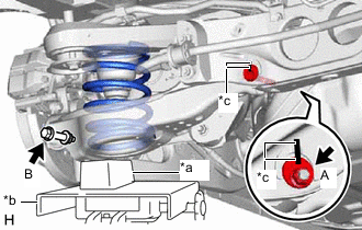
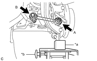
*a Wooden Block *b Jack *c Matchmark Place matchmarks on the No. 2 adjust cam, toe adjust cam sub-assembly and rear suspension member sub-assembly.
-
Support the rear No. 2 suspension arm assembly using a jack and wooden block.
CAUTION:
Do not jack up the rear No. 2 suspension arm assembly too high as the vehicle may fall.
Note
When jacking up the rear No. 2 suspension arm assembly, be sure to jack it up slowly.
-
Loosen the nut (A).
Note
Do not remove the nut.
-
Remove the bolt (B) and nut, and separate the rear No. 2 suspension arm assembly from the rear axle assembly.
Note
Because the nut has its own stopper, do not turn the nut. Loosen the bolt with the nut secured.
-
Slowly lower the rear No. 2 suspension arm assembly, and then remove the rear coil spring.
-
Remove the rear lower coil spring insulator from the rear No. 2 suspension arm assembly.
-
Remove the nut, No. 2 adjust cam, toe adjust cam sub-assembly and rear No. 2 suspension arm assembly.
-
-
REMOVE REAR NO. 1 SUSPENSION ARM ASSEMBLY (for 2WD)
-
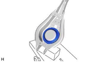
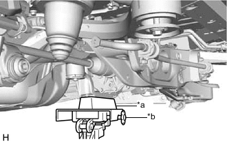
*a Attachment *b Jack Support the rear suspension member sub-assembly with a jack using an attachment or an equivalent tool as shown in the illustration.
CAUTION:
Do not jack up the rear suspension member sub-assembly too high as the vehicle may fall.
Note
-
Keep supporting the rear suspension member sub-assembly with a jack until the installation of the rear No. 1 suspension arm assembly has been completed.
-
When jacking up the rear suspension member sub-assembly, be sure to jack it up slowly.
-
-
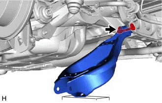
Remove the bolt, nut and rear lower suspension member stopper.
-

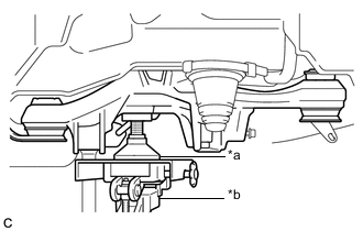
*a Wooden Block *b Jack Support the rear axle assembly with a jack using a wooden block as shown in the illustration.
CAUTION:
Do not jack up the rear axle assembly too high as the vehicle may fall.
Note
-
Keep supporting the rear axle assembly with a jack until the installation of the rear No. 1 suspension arm assembly has been completed.
-
When jacking up the rear axle assembly, be sure to jack it up slowly.
-
-
Remove the nut (A) and spacer.
-
Remove the bolt (B), nut and rear No. 1 suspension arm assembly.
Note
Because the nut has its own stopper, do not turn the nut. Loosen the bolt with the nut secured.
-
-
REMOVE REAR NO. 1 SUSPENSION ARM ASSEMBLY (for AWD)
-
*a Wooden Block *b Jack Support the rear differential carrier assembly with a jack using a wooden block as shown in the illustration.
CAUTION:
Do not jack up the rear differential carrier assembly too high as the vehicle may fall.
Note
-
Keep supporting the rear differential carrier assembly with a jack until the installation of the rear No. 1 suspension arm assembly has been completed.
-
When jacking up the rear differential carrier assembly, be sure to jack it up slowly.
-
-
Remove the bolt, nut and rear lower suspension member stopper.
-
*a Wooden Block *b Jack Support the rear axle assembly with a jack using a wooden block as shown in the illustration.
CAUTION:
Do not jack up the rear axle assembly too high as the vehicle may fall.
Note
-
Keep supporting the rear axle assembly with a jack until the installation of the rear No. 1 suspension arm assembly has been completed.
-
When jacking up the rear axle assembly, be sure to jack it up slowly.
-
-
Remove the nut (A) and spacer.
-
Remove the bolt (B), nut and rear No. 1 suspension arm assembly.
Note
Because the nut has its own stopper, do not turn the nut. Loosen the bolt with the nut secured.
-