FRONT SUSPENSION MEMBER(When Using the Engine Support Bridge for 2GR-FKS) REMOVAL

PROCEDURE
-
PRECAUTION
Note
After turning the engine switch off, waiting time may be required before disconnecting the cable from the negative (-) battery terminal. Therefore, make sure to read the disconnecting the cable from the negative (-) battery terminal notices before proceeding with work.
-
ALIGN FRONT WHEELS FACING STRAIGHT AHEAD
-
SECURE STEERING WHEEL
-
DISCONNECT CABLE FROM NEGATIVE BATTERY TERMINAL
Note
When disconnecting the cable, some systems need to be initialized after the cable is reconnected.
-
REMOVE FRONT WHEELS
-
REMOVE WINDSHIELD WIPER MOTOR AND LINK ASSEMBLY
-
REMOVE OUTER COWL TOP PANEL SUB-ASSEMBLY
for LHD: Click here
for RHD: Click here
-
REMOVE NO. 1 ENGINE UNDER COVER
-
REMOVE NO. 2 ENGINE UNDER COVER
-
REMOVE FRONT FLOOR COVER LH
-
SEPARATE FRONT FENDER LINER LH
-
SEPARATE FRONT FENDER LINER RH
-
REMOVE FRONT FENDER APRON SEAL LH
-
REMOVE FRONT FENDER APRON SEAL RH
-
REMOVE RADIATOR SIDE DEFLECTOR SEAL LH
-
REMOVE RADIATOR SIDE SEAL RH
-
REMOVE COOL AIR INTAKE DUCT SEAL
-
REMOVE V-BANK COVER SUB-ASSEMBLY
-
REMOVE INLET AIR CLEANER ASSEMBLY
-
DRAIN ENGINE COOLANT
-
REMOVE AIR CLEANER ASSEMBLY WITH AIR CLEANER HOSE
-
REMOVE THROTTLE BODY WITH MOTOR ASSEMBLY
-
REMOVE THROTTLE BODY GASKET
-
REMOVE BATTERY
-
DISCONNECT ENGINE WIRE
-
Remove the 2 bolts and nut, disconnect the engine wire from the automatic transaxle case sub-assembly.
-
-
SEPARATE BRAKE MASTER CYLINDER RESERVOIR ASSEMBLY (for LHD)
-
DISCONNECT VENTILATION HOSE
-
DISCONNECT PURGE VALVE (PURGE VSV)
-
REMOVE NO. 2 SURGE TANK STAY
-
REMOVE INTAKE AIR SURGE TANK ASSEMBLY
-
REMOVE AIR SURGE TANK TO INTAKE MANIFOLD GASKET
-
REMOVE WIRE HARNESS CLAMP BRACKET
for 2WD: Click here
for AWD: Click here
-
REMOVE FRONT NO. 3 EXHAUST PIPE SUB-ASSEMBLY
-
REMOVE NO. 1 EXHAUST PIPE SUPPORT BRACKET (for Lower Side)
-
REMOVE FRONT EXHAUST PIPE ASSEMBLY
-
REMOVE PROPELLER WITH CENTER BEARING SHAFT ASSEMBLY (for AWD)
-
SEPARATE FRONT STABILIZER LINK ASSEMBLY LH
-
SEPARATE FRONT STABILIZER LINK ASSEMBLY RH
Tech Tips
Perform the same procedure as for the LH side.
-
SEPARATE STEERING INTERMEDIATE SHAFT ASSEMBLY
-
SEPARATE TIE ROD ASSEMBLY LH
-
SEPARATE TIE ROD ASSEMBLY RH
Tech Tips
Use the same procedure described for the LH side.
-
SEPARATE FRONT LOWER NO. 1 SUSPENSION ARM SUB-ASSEMBLY LH
-
SEPARATE FRONT LOWER NO. 1 SUSPENSION ARM SUB-ASSEMBLY RH
Tech Tips
Perform the same procedure as for the LH side.
-
REMOVE FRONT NO. 1 STABILIZER BRACKET LH (for AWD)
-
Remove the 2 bolts and front No. 1 stabilizer bracket LH from the front frame assembly.
-
-
REMOVE FRONT NO. 1 STABILIZER BRACKET RH (for AWD)
Tech Tips
Perform the same procedure as for the LH side.
-
SEPARATE FRONT STABILIZER BAR WITH FRONT STABILIZER LINK ASSEMBLY (for AWD)
-
SEPARATE STEERING LINK ASSEMBLY (for AWD)
-
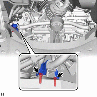
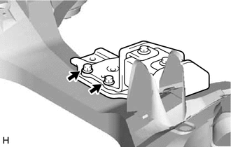
SEPARATE TRANSMISSION OIL THERMOSTAT
-
Remove the 2 bolts and separate the transmission oil thermostat from the front frame assembly.
-
-
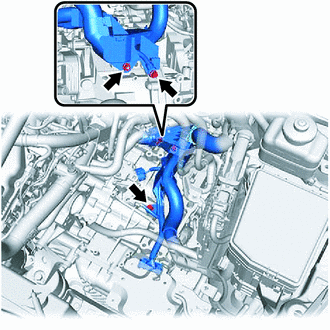
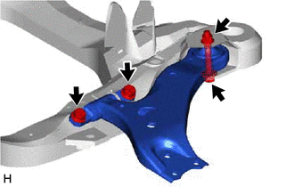
SEPARATE FRONT ENGINE MOUNTING INSULATOR ASSEMBLY
-
Remove the hole plug.
-
Remove the 3 nuts and separate the front engine mounting insulator assembly.
-
-
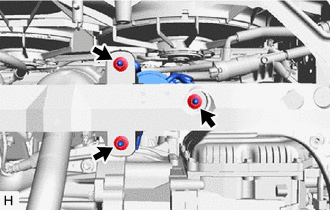
SEPARATE ENGINE MOUNTING INSULATOR LH
-
Remove the 2 hole plugs.
-
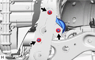
Remove the 3 nuts and separate the engine mounting insulator LH from the front frame assembly.
-
-
SEPARATE ENGINE MOUNTING INSULATOR RH
-
Remove the 2 hole plugs.
-
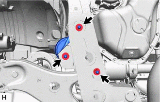
Remove the 3 nuts and separate the engine mounting insulator RH from the front frame assembly.
-
-
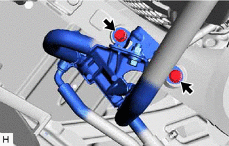
SEPARATE REAR ENGINE MOUNTING INSULATOR ASSEMBLY
-
Remove the 2 hole plugs.
-
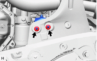
Remove the 2 nuts and separate the rear engine mounting insulator assembly from the front frame assembly.
-
-
INSTALL ENGINE HANGERS
for 2WD: Click here
for AWD: Click here
-
INSTALL ENGINE SUPPORT BRIDGE
for 2WD: Click here
for AWD: Click here
-
INSTALL BELT
for 2WD: Click here
for AWD: Click here
-
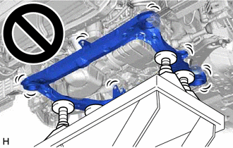
REMOVE FRONT FRAME ASSEMBLY
-
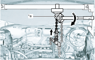
*a Chain Block Assembly 
Turn Using the chain block assembly, lift the engine with automatic transaxle assembly until the engine is slightly raised off the front frame assembly.
Note
-
When suspending the engine with automatic transaxle assembly, do not tighten the chain block assembly more than 41 N*m (418 kgf*cm, 30 ft.*lbf).
-
Lift the engine with automatic transaxle assembly until the engine is slightly raised off the front frame assembly.
-
Do not lift the engine with automatic transaxle assembly excessively.
-
Do not shake the engine with automatic transaxle assembly excessively while it is suspended.
-
-

*a Engine Lifter *b Attachment 
Attachment Placement Location Support the front frame assembly with an engine lifter using 4 attachments or equivalent tools as shown in the illustration.
CAUTION:
-
The front frame assembly is a very heavy component. Make sure that it is supported securely.
-
If the front frame assembly is not securely supported, it may drop, resulting in serious injury.
Note
Use attachments to keep the front frame assembly level.
-
-
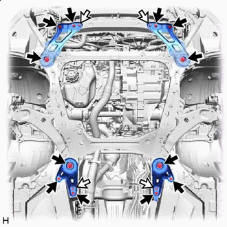

Bolt 
Nut Remove the 6 bolts, 2 nuts and frame side rail plate RH and frame side rail plate LH.
-
Remove the 6 bolts, 2 nuts and front suspension member rear brace RH and front suspension member rear brace LH.
-
Slowly lower the front frame assembly.
Note
When lowering the front frame assembly, be careful not to damage the vehicle body or other components installed to the vehicle.
-
-
REMOVE FRONT NO. 1 STABILIZER BRACKET LH (for 2WD)
-
Remove the 2 bolts and front No. 1 stabilizer bracket LH from the front frame assembly.
-
-
REMOVE FRONT NO. 1 STABILIZER BRACKET RH (for 2WD)
Tech Tips
Perform the same procedure as for the LH side.
-
REMOVE FRONT STABILIZER BAR WITH FRONT STABILIZER LINK ASSEMBLY (for 2WD)
-
Remove the front stabilizer bar with 2 front No. 2 stabilizer brackets, 2 front No. 1 stabilizer bar bushings and 2 front stabilizer link assemblies from the front frame assembly.
-
-
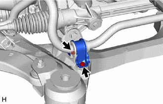
REMOVE STEERING LINK ASSEMBLY (for 2WD)
-
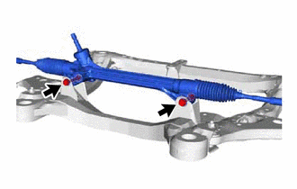
Remove the 2 bolts, 2 nuts and steering link assembly from the front frame assembly.
Note
Keep the nut from rotating while turning the bolt because the nut has its own stopper.
-
-
REMOVE FRONT LOWER NO. 1 SUSPENSION ARM SUB-ASSEMBLY LH
-
Remove the 3 bolts, nut and front lower No. 1 suspension arm sub-assembly LH from the front frame assembly.
Note
Because the nut has its own stopper, do not turn the nut. Loosen the bolt with the nut secured.
-
-
REMOVE FRONT LOWER NO. 1 SUSPENSION ARM SUB-ASSEMBLY RH
Tech Tips
Perform the same procedure as for the LH side.
-
REMOVE NO. 2 FRAME CROSSMEMBER DYNAMIC DAMPER
-
for 2WD:
-
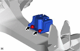
Remove the 2 bolts and No. 2 frame crossmember dynamic damper from the front frame assembly.
-
-
for AWD:
-
Remove the 2 bolts and No. 2 frame crossmember dynamic damper from the front frame assembly.
-
-
-
REMOVE FRONT SUSPENSION MEMBER BODY MOUNTING FRONT STOPPER
-
Remove the 2 front suspension member body mounting front stoppers from the front frame assembly.
-
-
REMOVE FRONT SUSPENSION MEMBER BODY MOUNTING REAR STOPPER
-
Remove the 2 front suspension member body mounting rear stoppers from the front frame assembly.
-
-
REMOVE FRONT SUSPENSION MEMBER BODY MOUNTING FRONT CUSHION
-
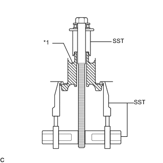
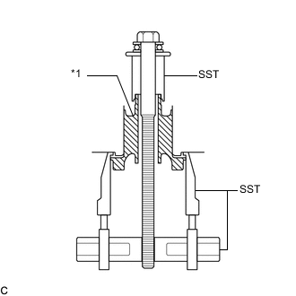
*1 Front Suspension Member Body Mounting Front Cushion Install SST as shown in the illustration.
- SST
- 09830-10010 ( 09830-01010, 09830-01040, 09830-01050 )
- 09950-40011 ( 09951-04020, 09952-04010, 09954-04010, 09955-04011, 09958-04011 )
-
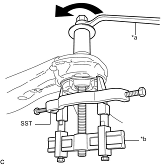
*a Turn *b Hold Using SST, remove each front suspension member body mounting front cushion from the front frame assembly.
Note
-
Make sure that the claws of SST are securely engaged to the mounting cushion.
-
Tighten SST slowly and evenly.
-
Be careful as the mounting cushion may fly out.
-
The mounting cushion cannot be reused.
-
-
-
REMOVE FRONT SUSPENSION MEMBER BODY MOUNTING REAR CUSHION LH
-
*1 Front Suspension Member Body Mounting Rear Cushion LH Install SST as shown in the illustration.
- SST
- 09830-10010 ( 09830-01010, 09830-01040, 09830-01050 )
- 09950-40011 ( 09951-04020, 09952-04010, 09954-04010, 09955-04011, 09958-04011 )
-
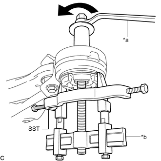
*a Turn *b Hold Using SST, remove the front suspension member body mounting rear cushion LH from the front frame assembly.
Note
-
Make sure that the claws of SST are securely engaged to the mounting cushion.
-
Tighten SST slowly and evenly.
-
Be careful as the mounting cushion may fly out.
-
The mounting cushion cannot be reused.
-
-
-
REMOVE FRONT SUSPENSION MEMBER BODY MOUNTING REAR CUSHION RH
Tech Tips
Perform the same procedure as for the LH side.
-
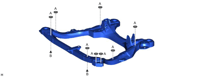
REMOVE HOLE PLUG
-
Remove the 10 hole plugs from the front frame assembly.
Tech Tips
There are 2 different shapes of hole plug.
-