FRONT LOWER SUSPENSION ARM(for 1AR-FE) REMOVAL
PROCEDURE
-
PRECAUTION
Note
After turning the ignition switch off, waiting time may be required before disconnecting the cable from the negative (-) battery terminal. Therefore, make sure to read the disconnecting the cable from the negative (-) battery terminal notices before proceeding with work.
-
DISCONNECT CABLE FROM NEGATIVE BATTERY TERMINAL
Note
When disconnecting the cable, some systems need to be initialized after the cable is reconnected.
-
REMOVE NO. 1 ENGINE COVER SUB-ASSEMBLY
-
REMOVE RADIATOR SIDE DEFLECTOR SEAL LH
-
REMOVE RADIATOR SIDE SEAL RH
-
REMOVE COOL AIR INTAKE DUCT SEAL
-
REMOVE INLET AIR CLEANER ASSEMBLY
-
REMOVE AIR CLEANER CAP WITH AIR CLEANER HOSE
-
REMOVE AIR CLEANER FILTER ELEMENT SUB-ASSEMBLY
-
REMOVE AIR CLEANER CASE SUB-ASSEMBLY
-
REMOVE BATTERY
-
SEPARATE NO. 2 ENGINE WIRE
-
Disengage the clamp and separate the No. 2 engine wire.
-
-
REMOVE AIR CLEANER BRACKET
-
Remove the 2 bolts and air cleaner bracket.
-
-
REMOVE FRONT WHEELS
-
REMOVE NO. 1 ENGINE UNDER COVER
-
REMOVE NO. 2 ENGINE UNDER COVER
-
REMOVE FRONT FENDER APRON SEAL LH (for LH Side)
-
REMOVE FRONT FENDER APRON SEAL RH (for RH Side)
-
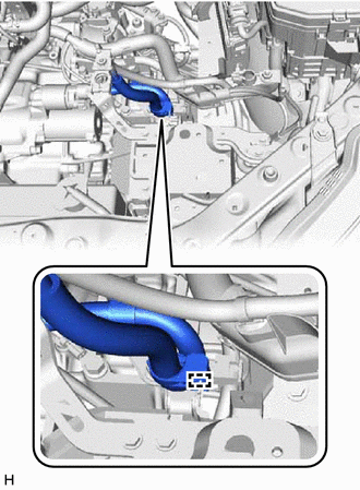
SEPARATE FRONT ENGINE MOUNTING INSULATOR
-
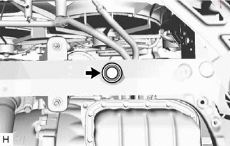
Remove the hole plug.
-
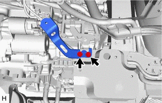
Remove the 3 nuts to separate the front engine mounting insulator from the front frame assembly.
-
-
REMOVE NO. 2 ENGINE MOUNTING STAY RH
-
REMOVE ENGINE MOVING CONTROL ROD BRACKET
-
REMOVE ENGINE MOUNTING INSULATOR LH (for LH Side)
-
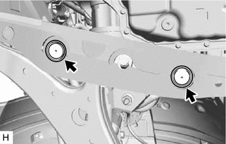
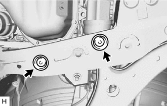
Remove the 2 hole plugs.
-
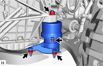
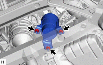
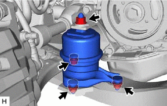
Remove the 4 nuts from the engine mounting insulator LH.
-
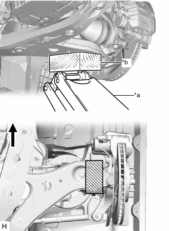
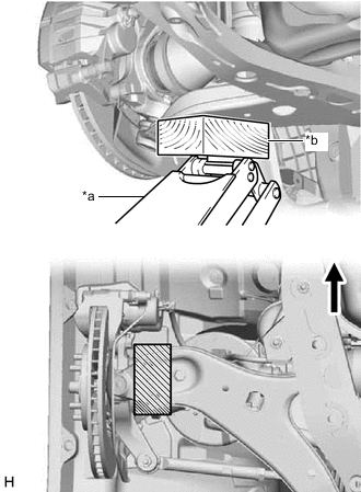
*a Jack *b Wooden Block 
Front of the Vehicle 
Wooden Block Placement Location Using a jack and a wooden block, support the front lower No. 1 suspension arm sub-assembly LH at the position shown in the illustration.
-
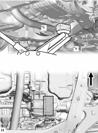
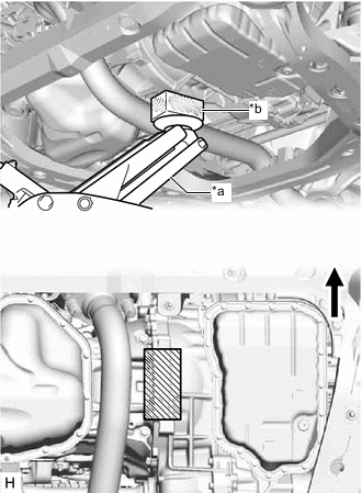
*a Jack *b Wooden Block Front of the Vehicle Wooden Block Placement Location Using a jack and a wooden block, support the engine assembly with transaxle at the position shown in the illustration.
-
While ensuring that the engine assembly with transaxle does not interfere with surrounding components, jack up the engine assembly with transaxle and front lower No. 1 suspension arm sub-assembly LH to the position where the engine mounting insulator LH can be removed.
CAUTION:
Do not jack up the front lower No. 1 suspension arm sub-assembly LH too high as the vehicle may fall.
Note
-
Do not position the wooden block under the oil pan.
-
Do not damage the components surrounding the engine assembly with transaxle.
-
Do not damage the front drive shaft assembly.
-
Tilt the engine assembly with transaxle as little as possible.
-
Ensure that the jack and wooden block are stable.
-
Make sure to perform this operation with the vehicle kept as low as possible.
Tech Tips
Jack up the front lower No. 1 suspension arm sub-assembly LH to prevent damage to the front drive shaft assembly.
-
-
Remove the engine mounting insulator LH from the front frame assembly.
-
Lower the engine assembly with transaxle to its original position.
Note
-
Do not damage the components surrounding the engine assembly with transaxle.
-
Ensure that the jack and wooden block are stable.
-
Keep the engine assembly with transaxle supported until installation of the engine mounting insulator LH is complete.
-
-
Remove the jack and wooden block that are used to support the front lower No. 1 suspension arm sub-assembly LH.
-
-
REMOVE FRONT LOWER NO. 1 SUSPENSION ARM SUB-ASSEMBLY LH (for LH Side)
-
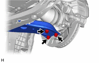
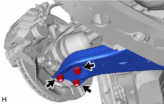
Remove the bolt and 2 nuts, and separate the front lower No. 1 suspension arm sub-assembly LH from the front lower ball joint assembly.
-
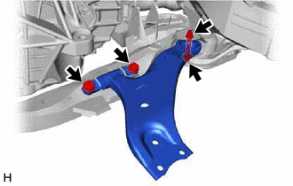
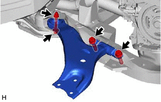
Remove the 3 bolts, nut and front lower No. 1 suspension arm sub-assembly LH from the front frame assembly.
Note
Because the nut has its own stopper, do not turn the nut. Loosen the bolt with the nut secured.
-
Remove the front lower arm bushing stopper from the front lower No. 1 suspension arm sub-assembly LH.
-
-
REMOVE ENGINE MOUNTING INSULATOR RH (for RH Side)
-
Remove the 2 hole plugs.
-
Remove the 4 nuts from the engine mounting insulator RH.
-
*a Jack *b Wooden Block Front of the Vehicle Wooden Block Placement Location Using a jack and a wooden block, support the front lower No. 1 suspension arm sub-assembly RH at the position shown in the illustration.
-
*a Jack *b Wooden Block Front of the Vehicle Wooden Block Placement Location Using a jack and a wooden block, support the engine assembly with transaxle at the position shown in the illustration.
-
While ensuring that the engine assembly with transaxle does not interfere with surrounding components, jack up the engine assembly with transaxle and front lower No. 1 suspension arm sub-assembly RH to the position where the engine mounting insulator RH can be removed.
CAUTION:
Do not jack up the front lower No. 1 suspension arm sub-assembly RH too high as the vehicle may fall.
Note
-
Do not position the wooden block under the oil pan.
-
Do not damage the components surrounding the engine assembly with transaxle.
-
Do not damage the front drive shaft assembly.
-
Tilt the engine assembly with transaxle as little as possible.
-
Ensure that the jack and wooden block are stable.
-
Make sure to perform this operation with the vehicle kept as low as possible.
Tech Tips
Jack up the front lower No. 1 suspension arm sub-assembly RH to prevent damage to the front drive shaft assembly.
-
-
Remove the engine mounting insulator RH from the front frame assembly.
-
Lower the engine assembly with transaxle to its original position.
Note
-
Do not damage the components surrounding the engine assembly with transaxle.
-
Ensure that the jack and wooden block are stable.
-
Keep the engine assembly with transaxle supported until installation of the engine mounting insulator RH is complete.
-
-
Remove the jack and the wooden block that are used to support the front lower No. 1 suspension arm sub-assembly RH.
-
-
REMOVE FRONT LOWER NO. 1 SUSPENSION ARM SUB-ASSEMBLY RH (for RH Side)
-
Remove the bolt and 2 nuts, and separate the front lower No. 1 suspension arm sub-assembly RH from the front lower ball joint assembly.
-
Remove the 3 bolts, nut and front lower No. 1 suspension arm sub-assembly RH from the front frame assembly.
Note
Because the nut has its own stopper, do not turn the nut. Loosen the bolt with the nut secured.
-
Remove the front lower arm bushing stopper from the front lower No. 1 suspension arm sub-assembly RH.
-