FRONT SHOCK ABSORBER INSTALLATION

CAUTION / NOTICE / HINT
Tech Tips
-
Use the same procedure for the RH side and LH side.
-
The procedure listed below is for the LH side.
PROCEDURE
-
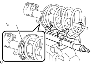
INSTALL FRONT LOWER COIL SPRING INSULATOR
-
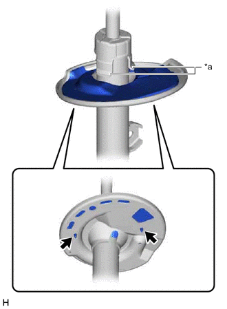
*a Claw 
Positioning Pin Install the front lower coil spring insulator to the front shock absorber assembly.
Note
-
When installing the front lower coil spring insulator, fit the insulator to the depression of the spring seat and insert the positioning pin into the hole.
-
When installing the front lower coil spring insulator, make sure that the front lower coil spring insulator does not get caught on the claws of the front shock absorber assembly.
-
-
-
INSTALL FRONT SPRING BUMPER
-
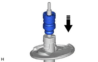
Install the front spring bumper to the front shock absorber assembly.
Note
Face the smaller diameter end of the front spring bumper downward.
-
-
INSTALL FRONT COIL SPRING
-
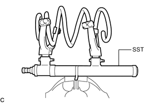
Secure SST in a vise.
- SST
- 09727-00050
- 09727-30021 ( 09727-00010, 09727-00031 )
-
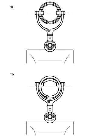
*a Correct *b Incorrect Attach the arms of SST to the diameter of the front coil spring.
CAUTION:
-
Make sure that the front coil spring is installed so that the distance between the upper and lower arms of SST is at the maximum.
-
Make sure that the claws of the arms are securely attached.
-
-
Using SST, compress the front coil spring.
CAUTION:
-
If the front coil spring bends during compression, immediately stop compression and reinstall SST.
-
Do not excessively compress the front coil spring so that the coils contact each other.
-
Do not use an impact wrench. It will damage SST.
-
-
*a Depression Install the front coil spring to the front shock absorber assembly.
Note
Make sure to fit the end of the front coil spring that has the larger diameter into the depression of the front lower coil spring insulator.
-
-
INSTALL FRONT SPRING SEAT SUB-ASSEMBLY WITH INSULATOR
-
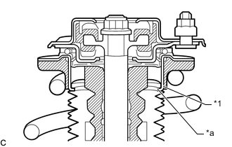
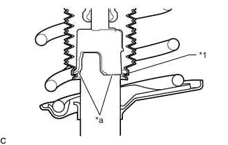
*1 Strut Mounting Bearing *a Top End of the Insulator (Shock Absorber Dust Cover) Install the front spring seat sub-assembly with insulator to the front shock absorber assembly.
Note
Make sure that the top end of the insulator (shock absorber dust cover) and the strut mounting bearing are securely attached.
-
-
INSTALL FRONT SUSPENSION SUPPORT SUB-ASSEMBLY
-
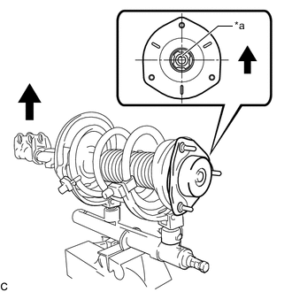
*a Slot Outside of the Vehicle Install the front suspension support sub-assembly as shown in the illustration.
Tech Tips
Check that the slot on the piston rod and the slot on the front suspension support sub-assembly are aligned.
-
Temporarily tighten a new front support to front shock absorber nut.
-
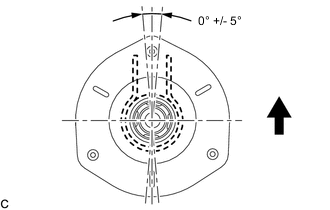
Outside of the Vehicle While aligning the stud bolt of the front suspension support sub-assembly and the front shock absorber lower bracket, remove SST from the front coil spring.
Note
-
Do not use an impact wrench. It will damage SST.
-
When installing the front suspension support sub-assembly, ensure that any misalignment between the front shock absorber lower bracket and the stud bolt is within +/- 5°. Use the stud bolt that is closest to the outside of the vehicle.
-
-
-
CONNECT FRONT SPRING SEAT SUB-ASSEMBLY WITH INSULATOR
-
*1 Front Spring Seat Sub-assembly with Insulator *a Claw Connect the end of the insulator of the front spring seat sub-assembly with insulator with the claws of the front shock absorber assembly.
Note
-
Make sure that the end of the insulator is securely attached to the claws of the front shock absorber assembly.
-
Make sure there is no excessive damage to the bellows of the insulator.
-
Do not allow oil, grease, etc., to contact the insulator.
-
If oil or grease has adhered, wipe clean with a cloth. Do not use an alcohol based cleaner.
-
-
-
INSTALL FRONT SHOCK ABSORBER WITH COIL SPRING
-
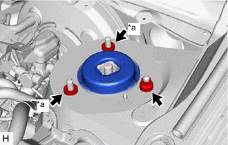
*a Spacer Install the front shock absorber with coil spring (upper side) with the nut and 2 spacers.
- Torque:
- 85 N*m { 867 kgf*cm, 63 ft.*lbf }
-
Install the front shock absorber with coil spring (lower side) to the steering knuckle with the 2 bolts and 2 nuts.
- Torque:
- 290 N*m { 2957 kgf*cm, 214 ft.*lbf }
Note
While keeping the bolts from rotating, tighten the nuts.
Tech Tips
The bolts can be installed in either direction, however, make sure that they are both installed in the same direction.
-
-
INSTALL FRONT STABILIZER LINK ASSEMBLY
-
Install the front stabilizer link assembly to the front shock absorber assembly with the nut.
- Torque:
- 74 N*m { 755 kgf*cm, 55 ft.*lbf }
Tech Tips
If the ball joint turns together with the nut, use a 6 mm hexagon wrench to hold the stud bolt.
-
-
INSTALL FRONT SPEED SENSOR
-
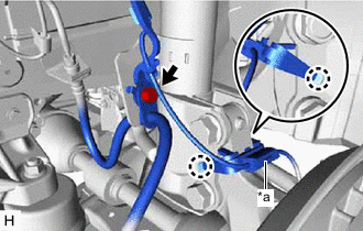
*a Sensor Clamp Install the front speed sensor and front flexible hose to the front shock absorber assembly with the bolt.
- Torque:
- 18.8 N*m { 192 kgf*cm, 14 ft.*lbf }
Note
Do not twist the front speed sensor and front flexible hose when installing them.
Tech Tips
Install the front speed sensor harness bracket first and then the front flexible hose.
-
Engage the 2 claws to install the sensor clamp.
-
-
INSTALL OUTER COWL TOP PANEL SUB-ASSEMBLY (for LHD)
-
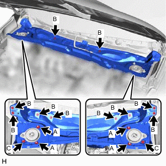
Install the outer cowl top panel sub-assembly with the 10 bolts and 6 nuts.
- Torque:
- Nut (A)
- 85 N*m { 867 kgf*cm, 63 ft.*lbf }
- Bolt (B)
- 5.5 N*m { 56 kgf*cm, 49 in.*lbf }
- Nut (C)
- 5.5 N*m { 56 kgf*cm, 49 in.*lbf }
-
Engage the 6 clamps to install the wire harness to the outer cowl top panel sub-assembly.
-
Connect the connector.
-
-
INSTALL OUTER COWL TOP PANEL SUB-ASSEMBLY (for RHD)
-
Install the outer cowl top panel sub-assembly with the 10 bolts and 6 nuts.
- Torque:
- Nut (A)
- 85 N*m { 867 kgf*cm, 63 ft.*lbf }
- Bolt (B)
- 5.5 N*m { 56 kgf*cm, 49 in.*lbf }
- Nut (C)
- 5.5 N*m { 56 kgf*cm, 49 in.*lbf }
-
Engage the 2 clamps to install the wire harness to the outer cowl top panel sub-assembly.
-
-
FULLY TIGHTEN FRONT SUPPORT TO FRONT SHOCK ABSORBER NUT
-
Fully tighten the front support to front shock absorber nut.
- Torque:
- 70 N*m { 714 kgf*cm, 52 ft.*lbf }
Note
Perform this step only when the front shock absorber with coil spring has been disassembled.
-
-
INSTALL WINDSHIELD WIPER MOTOR AND LINK ASSEMBLY
-
INSTALL FRONT WHEEL
- Torque:
- 103 N*m { 1050 kgf*cm, 76 ft.*lbf }
-
STABILIZE SUSPENSION
-
Lower the vehicle.
-
Bounce the vehicle up and down several times to stabilize the suspension.
-
-
INSPECT AND ADJUST FRONT WHEEL ALIGNMENT