REAR AXLE CARRIER(for AWD) INSTALLATION

CAUTION / NOTICE / HINT
Tech Tips
-
Use the same procedure for the RH side and LH side.
-
The procedure listed below is for the LH side.
PROCEDURE
-
INSTALL LOWER CONTROL ARM PIN
-
Secure the rear axle carrier sub-assembly in a vise using aluminum plates.
Note
Do not overtighten the vise.
-
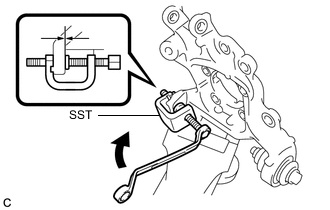
Using SST, install a new lower control arm pin to the rear axle carrier sub-assembly as shown in the illustration.
- SST
- 09650-17011
-
-
TEMPORARILY INSTALL REAR AXLE CARRIER SUB-ASSEMBLY
-
Secure the rear axle carrier sub-assembly in a vise using aluminum plates.
Note
Do not overtighten the vise.
-
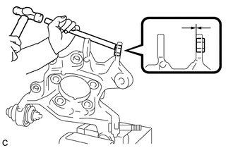
Using a brass bar and a hammer, push out the bushing until it is positioned as shown in the illustration.
Tech Tips
Pushing out the bushing makes it easier to install the rear axle carrier sub-assembly.
-
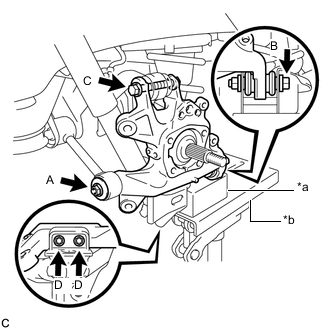
*a Wooden Block *b Jack Temporarily install the rear axle carrier sub-assembly to the rear No. 1 suspension arm assembly with the spacer and nut (A).
Note
Fully tighten the nut (A) after stabilizing the suspension.
-
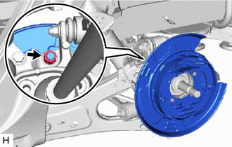
Install the rear axle carrier sub-assembly to the rear No. 2 suspension arm assembly with the bolt (B) and nut.
- Torque:
- 100 N*m { 1020 kgf*cm, 74 ft.*lbf }
Note
-
Insert the bolt with the threaded end facing the front of the vehicle.
-
Because the nut has its own stopper, do not turn the nut. Tighten the bolt with the nut secured.
-
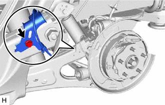
Install the rear axle carrier sub-assembly to the rear upper control arm assembly with the bolt (C) and nut.
- Torque:
- 145 N*m { 1479 kgf*cm, 107 ft.*lbf }
Note
-
Insert the bolt with the threaded end facing the rear of the vehicle.
-
Because the nut has its own stopper, do not turn the nut. Tighten the bolt with the nut secured.
-
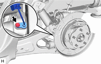
Install the rear axle carrier sub-assembly to the rear lower shock absorber bracket sub-assembly with the 2 bolts (D).
- Torque:
- 100 N*m { 1020 kgf*cm, 74 ft.*lbf }
-
Slowly lower the rear No. 2 suspension arm assembly.
-
-
TEMPORARILY INSTALL PARKING BRAKE ASSEMBLY
-
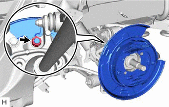
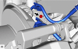
Temporarily install the parking brake assembly to the rear axle carrier sub-assembly with the nut.
Note
-
Do not twist the parking brake cable when installing the parking brake assembly.
-
Fully tighten the nut after installing the rear trailing arm assembly.
-
-
-
INSTALL REAR TRAILING ARM ASSEMBLY
-
INSTALL PARKING BRAKE ASSEMBLY
-
Install the parking brake assembly with the nut.
- Torque:
- 160 N*m { 1632 kgf*cm, 118 ft.*lbf }
-
-
INSTALL REAR AXLE HUB AND BEARING ASSEMBLY
-
INSTALL REAR SPEED SENSOR
-
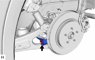
Install the rear speed sensor to the rear trailing arm assembly with the bolt.
- Torque:
- 8.0 N*m { 82 kgf*cm, 71 in.*lbf }
Note
Do not twist the rear speed sensor when installing it.
-
Install the rear speed sensor to the rear axle carrier sub-assembly with the bolt.
- Torque:
- 8.5 N*m { 87 kgf*cm, 75 in.*lbf }
Note
Do not twist the rear speed sensor when installing it.
-
-
INSTALL REAR DISC
-
INSTALL PARKING BRAKE SHOE ADJUSTING HOLE PLUG
-
INSTALL REAR DISC BRAKE CALIPER ASSEMBLY
-
Install the rear disc brake caliper assembly to the rear axle carrier sub-assembly with the 2 bolts.
- Torque:
- 95 N*m { 969 kgf*cm, 70 ft.*lbf }
-
Install the rear flexible hose to the rear upper control arm assembly with the bolt.
- Torque:
- 18.8 N*m { 192 kgf*cm, 14 ft.*lbf }
Note
-
Do not twist the rear flexible hose when installing it.
-
Do not damage the rear flexible hose when installing it.
-
If the rear flexible hose is damaged, replace it with a new one.
-
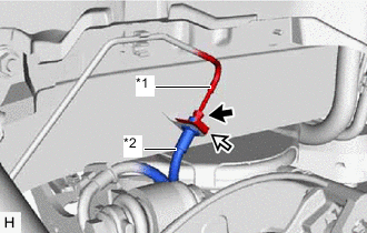
*1 Rear Brake Tube *2 Rear Flexible Hose 
Clip Install the rear flexible hose with a new clip.
Note
Install the clip as far as it will go.
-
Using a union nut wrench, connect the rear flexible hose to the rear brake tube while holding the rear flexible hose with a wrench.
- Torque:
- 15.2 N*m { 155 kgf*cm, 11 ft.*lbf }
Note
-
Do not kink or damage the brake line.
-
Do not allow any foreign matter such as dirt or dust to enter the brake line from the connecting parts.
-
Use the formula to calculate special torque values for situations where the union nut wrench is combined with a torque wrench.
-
-
INSTALL REAR AXLE SHAFT NUT
-
Clean the threaded parts on the rear drive shaft assembly and a new rear axle shaft nut using non-residue solvent.
Note
-
Be sure to perform this work even when using a new rear drive shaft assembly.
-
Keep the threaded parts free of oil and foreign matter.
-
-
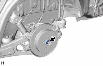
Using a 30 mm socket wrench, while applying the parking brakes, temporarily install the rear axle shaft nut.
- Torque:
- 294 N*m { 2998 kgf*cm, 217 ft.*lbf }
-
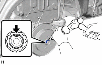
Using a chisel and hammer, stake the rear axle shaft nut.
-
-
BLEED BRAKE LINE
-
STABILIZE SUSPENSION
-
INSTALL REAR NO. 1 SUSPENSION ARM ASSEMBLY
-
Install the rear No. 1 suspension arm assembly with the nut.
- Torque:
- 145 N*m { 1479 kgf*cm, 107 ft.*lbf }
-
-
INSTALL REAR SUSPENSION ARM COVER
-
ADJUST PARKING BRAKE
-
INSTALL REAR WHEEL
- Torque:
- 103 N*m { 1050 kgf*cm, 76 ft.*lbf }
-
INSPECT AND ADJUST REAR WHEEL ALIGNMENT
-
CHECK FOR SPEED SENSOR SIGNAL