REAR AXLE CARRIER(for AWD) REMOVAL

CAUTION / NOTICE / HINT
Tech Tips
-
Use the same procedure for the RH side and LH side.
-
The procedure listed below is for the LH side.
PROCEDURE
-
REMOVE REAR WHEEL
-
DRAIN BRAKE FLUID
Note
If brake fluid leaks onto any painted surface, immediately wash it off.
-
REMOVE REAR SUSPENSION ARM COVER
-
REMOVE REAR AXLE SHAFT NUT
-
REMOVE REAR DISC BRAKE CALIPER ASSEMBLY
-
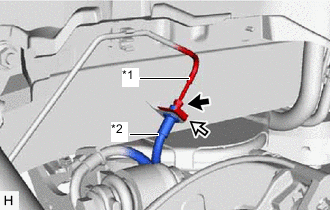
*1 Rear Brake Tube *2 Rear Flexible Hose 
Clip Using a union nut wrench, separate the rear flexible hose from the rear brake tube while holding the rear flexible hose with a wrench.
Note
-
Do not kink or damage the brake line.
-
Do not allow any foreign matter such as dirt or dust to enter the brake line from the connecting parts.
-
-
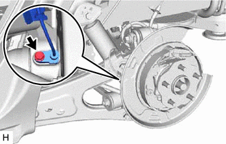
Remove the clip and separate the rear flexible hose.
-
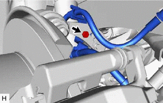
Remove the bolt and separate the rear flexible hose from the rear upper control arm assembly.
-
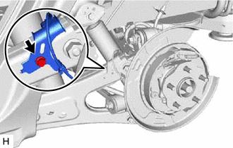
Remove the 2 bolts and rear disc brake caliper assembly with rear flexible hose.
-
-
REMOVE PARKING BRAKE SHOE ADJUSTING HOLE PLUG
-
REMOVE REAR DISC
-
SEPARATE REAR SPEED SENSOR
-
Remove the bolt and separate the rear speed sensor from the rear axle carrier sub-assembly.
Note
-
Prevent foreign matter from contacting the sensor tip.
-
Clean the speed sensor installation hole and the contact surfaces every time the speed sensor is removed.
-
Be careful not to damage the rear speed sensor.
-
-
Remove the bolt and separate the rear speed sensor from the rear trailing arm assembly.
-
-
REMOVE REAR AXLE HUB AND BEARING ASSEMBLY
-
LOOSEN PARKING BRAKE ASSEMBLY
-
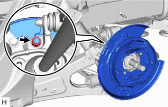
Loosen the nut to separate the parking brake assembly after removing the rear trailing arm assembly.
-
-
REMOVE REAR TRAILING ARM ASSEMBLY
-
SEPARATE PARKING BRAKE ASSEMBLY
-
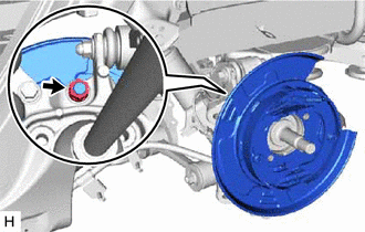
Remove the nut and separate the parking brake assembly from the rear axle carrier sub-assembly.
Note
Use wire or an equivalent tool to keep the parking brake assembly from hanging by the parking brake cable.
-
-
REMOVE REAR AXLE CARRIER SUB-ASSEMBLY
-
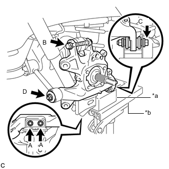
*a Wooden Block *b Jack Support the rear No. 2 suspension arm assembly using a jack and wooden block.
CAUTION:
Do not jack up the rear No. 2 suspension arm assembly too high as the vehicle may fall.
Note
-
When jacking up the rear No. 2 suspension arm assembly, be sure to jack it up slowly.
-
Keep supporting the rear No. 2 suspension arm assembly until the installation of the rear axle carrier sub-assembly has been completed.
-
-
Remove the 2 bolts (A), and separate the rear axle carrier sub-assembly from the rear lower shock absorber bracket sub-assembly.
-
Remove the bolt (B) and nut, and separate the rear upper control arm assembly from the rear axle carrier sub-assembly.
Note
Because the nut has its own stopper, do not turn the nut. Loosen the bolt with the nut secured.
-
Remove the bolt (C) and nut, and separate the rear axle carrier sub-assembly from the rear No. 2 suspension arm assembly.
Note
Because the nut has its own stopper, do not turn the nut. Loosen the bolt with the nut secured.
-
Remove the nut (D), spacer and rear axle carrier sub-assembly from the rear No. 1 suspension arm assembly.
Note
Use wire or an equivalent tool to keep the rear drive shaft assembly from hanging down.
-
-
REMOVE LOWER CONTROL ARM PIN
-
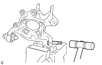
Secure the rear axle carrier sub-assembly in a vise using aluminum plates.
Note
Do not overtighten the vise.
-
Using a hammer, remove the lower control arm pin from the rear axle carrier sub-assembly.
-