REAR DIFFERENTIAL CARRIER ASSEMBLY REMOVAL

PROCEDURE
-
DRAIN DIFFERENTIAL OIL
-
REMOVE REAR AXLE CARRIER SUB-ASSEMBLY LH
-
REMOVE REAR DRIVE SHAFT ASSEMBLY LH
-
REMOVE REAR DRIVE SHAFT SNAP RING LH
-
TEMPORARILY INSTALL REAR AXLE CARRIER SUB-ASSEMBLY LH
-
*a Wooden Block *b Jack *c Spacer 
Bolt 
Nut Using a jack and wooden block, jack up the rear No. 2 suspension arm assembly LH to replicate standard vehicle height conditions.
CAUTION:
Do not jack up the rear No. 2 suspension arm assembly LH too high as the vehicle may fall.
-
Temporarily install the rear axle carrier sub-assembly LH with the 4 bolts, 3 nuts and spacer to the rear No. 1 suspension arm assembly LH, rear No. 2 suspension arm assembly LH, rear upper control arm assembly LH and rear lower shock absorber bracket sub-assembly LH.
-
Lower the jack.
-
-
REMOVE REAR AXLE CARRIER SUB-ASSEMBLY RH
-
REMOVE REAR DRIVE SHAFT ASSEMBLY RH
-
REMOVE REAR DRIVE SHAFT SNAP RING RH
-
TEMPORARILY INSTALL REAR AXLE CARRIER SUB-ASSEMBLY RH
Tech Tips
Use the same procedure for the RH side and LH side.
-
REMOVE NO. 2 ENGINE UNDER COVER
-
REMOVE FRONT FLOOR COVER LH
-
REMOVE FRONT CENTER FLOOR COVER
-
REMOVE WIRING HARNESS CLAMP BRACKET
-
REMOVE PROPELLER SHAFT GUARD (for Front Side)
-
REMOVE PROPELLER SHAFT GUARD (for Rear Side)
-
REMOVE PROPELLER WITH CENTER BEARING SHAFT ASSEMBLY
-
REMOVE TAIL EXHAUST PIPE ASSEMBLY
-
REMOVE STABILIZER LINK SUB-ASSEMBLY LH
-
REMOVE STABILIZER LINK SUB-ASSEMBLY RH
-
REMOVE REAR STABILIZER BAR
-
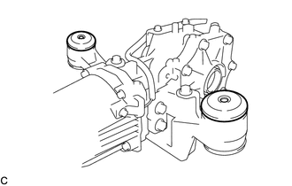
LOOSEN NO. 1 REAR DIFFERENTIAL SUPPORT
Tech Tips
Loosen the bolts only when removal of the No. 1 rear differential support is required.
-
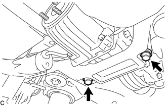
Loosen the 2 bolts.
-
-
REMOVE REAR DIFFERENTIAL CARRIER ASSEMBLY WITH DIFFERENTIAL SUPPORT
Note
-
Do not damage the contact surface when removing the rear differential carrier assembly with differential support.
-
The remaining oil may leak out when removing the rear differential carrier assembly with differential support.
-
Securely support the rear differential carrier assembly with differential support while performing this step to avoid excessively tilting or dropping the rear differential carrier assembly with differential support.
-
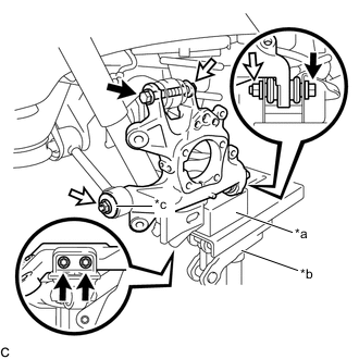
Remove the bolts and nuts with the rear differential carrier assembly with differential support secured.
-
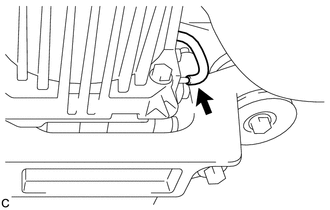
Disconnect the vacuum hose from the electro magnetic control coupling sub-assembly.
-
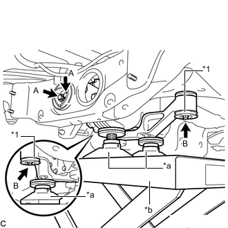
*1 Lower Rear Differential Mount Stopper *a Attachment *b Engine Lifter Support the rear differential carrier assembly with differential support with an engine lifter using 3 attachments or equivalent tools as shown in the illustration.
-
Remove the 2 bolts (A).
-
Remove the 2 bolts (B), 2 nuts and 2 lower rear differential mount stoppers from the No. 1 rear differential support.
Tech Tips
The nuts have tabs to prevent them from rotating.
-
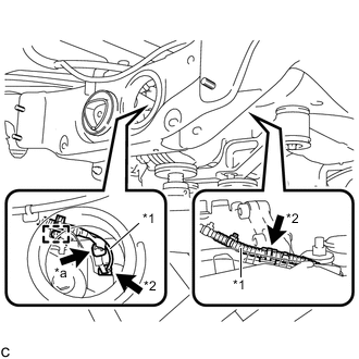
*1 Vacuum Hose *2 Clamp *a Connector Slightly lower the rear differential carrier assembly with differential support, remove the vacuum hose from the 2 clamps, disconnect the connector, and remove the clamp from the connector bracket.
-
Lower the rear differential carrier assembly with differential support slowly to remove the rear differential carrier assembly with differential support.
Note
Do not damage the vacuum hose and electro magnetic control coupling wire harness.
-
-
REMOVE DIFFERENTIAL SUPPORT
-
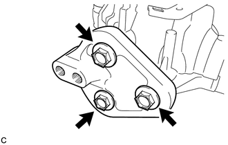
Remove the 3 bolts and rear differential support from the rear differential carrier assembly.
-
-
REMOVE UPPER REAR DIFFERENTIAL MOUNT STOPPER
-
Remove the 2 upper rear differential mount stoppers from the No. 1 rear differential support.
-
-
REMOVE NO. 1 REAR DIFFERENTIAL SUPPORT
-
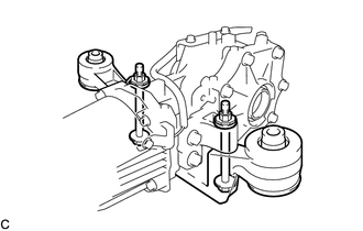
Remove the 2 bolts, 2 nuts and No. 1 rear differential support.
Tech Tips
The nuts have tabs to prevent them from rotating.
-