FRONT AXLE HUB REMOVAL

CAUTION / NOTICE / HINT
Tech Tips
-
Use the same procedure for the RH side and LH side.
-
The procedure listed below is for the LH side.
PROCEDURE
-
REMOVE FRONT WHEEL
-
REMOVE FRONT AXLE SHAFT NUT
for 1AR-FE: Click here
for 2GR-FKS: Click here
-
SEPARATE FRONT SPEED SENSOR
-
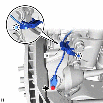
*a Sensor Clamp Disengage the 2 claws and separate the sensor clamp.
-
Remove the bolt and separate the front speed sensor from the steering knuckle.
Note
-
Prevent foreign matter from contacting the sensor tip.
-
Be careful not to damage the front speed sensor.
-
Clean the speed sensor installation hole and the contact surfaces every time the speed sensor is removed.
-
-
-
SEPARATE FRONT DISC BRAKE CALIPER ASSEMBLY
-
REMOVE FRONT DISC
-
SEPARATE TIE ROD ASSEMBLY
for 2WD: Click here
for AWD: Click here
-
SEPARATE FRONT DRIVE SHAFT ASSEMBLY
-
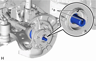
*a Matchmark Put matchmarks on the front drive shaft assembly and the front axle hub sub-assembly.
-
Using a plastic hammer, separate the front drive shaft assembly from the front axle assembly.
Note
Be careful not to damage the drive shaft boot.
Tech Tips
If it is difficult to separate the front drive shaft assembly from the front axle assembly, tap the end of the front drive shaft assembly using a brass bar and a hammer.
-
-
SEPARATE FRONT LOWER NO. 1 SUSPENSION ARM SUB-ASSEMBLY
-
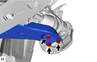
Remove the bolt and 2 nuts, and separate the front lower No. 1 suspension arm sub-assembly from the front lower ball joint assembly.
-
-
REMOVE FRONT AXLE ASSEMBLY
-
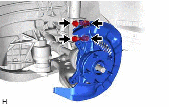
Remove the 2 bolts, 2 nuts and front axle assembly from the front shock absorber assembly.
Note
-
When removing the nuts, keep the bolts from rotating.
-
Be careful not to damage the drive shaft boot or speed sensor rotor.
-
-
-
REMOVE FRONT NO. 1 WHEEL BEARING DUST DEFLECTOR
-
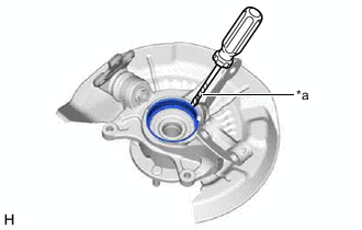
*a Protective Tape Using a screwdriver with its tip wrapped with protective tape, remove the front No. 1 wheel bearing dust deflector.
Note
Be careful not to damage the steering knuckle.
-
-
REMOVE FRONT AXLE HUB HOLE SNAP RING
-
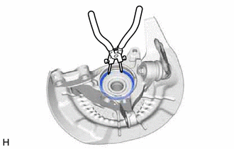
Using snap ring pliers, remove the front axle hub hole snap ring.
-
-
REMOVE FRONT AXLE HUB SUB-ASSEMBLY
-
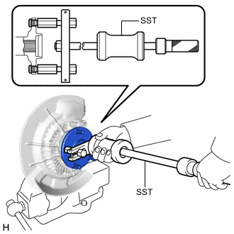
Secure the front axle assembly between aluminum plates in a vise.
Note
Do not overtighten the vise.
-
Using SST, remove the front axle hub sub-assembly.
- SST
- 09520-00031
-

Using SST and a press, remove the bearing inner race (outside) from the front axle hub sub-assembly.
- SST
- 09555-55010
- 09950-60010 ( 09951-00440 )
- 09950-70010 ( 09951-07100 )
Note
Be careful not to drop the front axle hub sub-assembly.
-
-
REMOVE FRONT DISC BRAKE DUST COVER SUB-ASSEMBLY
-
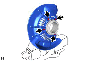
Remove the 4 bolts and front disc brake dust cover sub-assembly from the steering knuckle.
-
-
REMOVE FRONT AXLE HUB BEARING
-
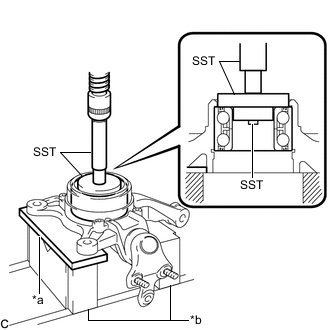
*a Steel Plate *b V-block Place the bearing inner race (outside) on the front axle hub bearing.
-
Using SST, a steel plate, V-blocks and a press, remove the front axle hub bearing from the steering knuckle.
- SST
- 09950-60010 ( 09951-00440, 09952-06010 )
- 09950-60020 ( 09951-00750 )
- 09950-70010 ( 09951-07100 )
Note
Keep the steering knuckle level.
-