PROPELLER SHAFT ASSEMBLY INSTALLATION

PROCEDURE
-
TEMPORARILY TIGHTEN PROPELLER WITH CENTER BEARING SHAFT ASSEMBLY
-
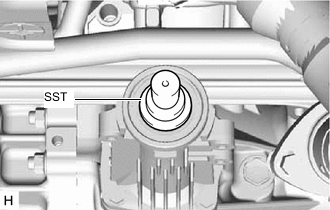
Remove SST from the transfer assembly.
-
Insert the propeller with center bearing shaft assembly into the transfer assembly.
Note
-
Be careful not to damage the transfer extension housing type T oil seal.
-
Be careful not to damage the universal joint boot when installing the propeller with center bearing shaft assembly.
-
-
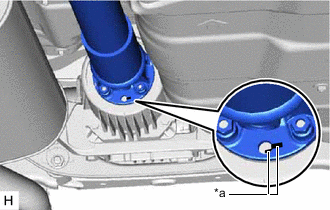
*a Matchmark Align the matchmarks on the electro magnetic control coupling sub-assembly and propeller with center bearing shaft assembly.
-
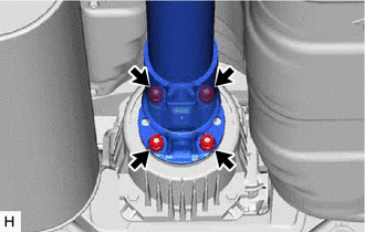
Temporarily install the 4 nuts and 4 washers.
Note
Do not allow grease to adhere to the 4 bolts, 4 nuts and 4 washers.
-
Temporarily install the propeller with center bearing shaft assembly with the 4 bolts, and 4 No. 2 center support bearing washers.
Note
-
Reuse the No. 2 center support bearing washers.
-
Do not allow grease to adhere to the 4 bolts or 4 No. 2 center support bearing washers.
-
-
Fully tighten the 4 nuts.
- Torque:
- 73.5 N*m { 749 kgf*cm, 54 ft.*lbf }
-
-
FULLY TIGHTEN PROPELLER WITH CENTER BEARING SHAFT ASSEMBLY
-
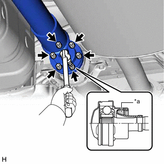
*a Piece of Cloth Remove the piece of cloth or equivalent from the universal joint flange.
-
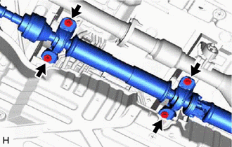
Using a 6 mm hexagon socket wrench, fully tighten the 6 cross groove joint set bolts.
- Torque:
- 26 N*m { 265 kgf*cm, 19 ft.*lbf }
-
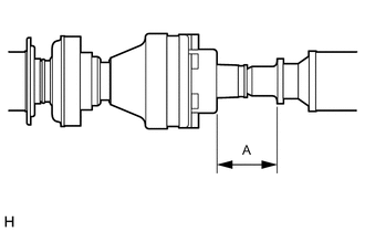
With the vehicle unloaded, adjust the distance (A) between the rear side of the cover and shaft as shown in the illustration.
Distance (A) 58 mm (2.28 in.) -
With the vehicle unloaded, adjust the front and rear distance (A) between the edge surface of the No. 2 center support bearing assembly and the edge surface of the cushion respectively as shown in the illustration, and then tighten the bolts.
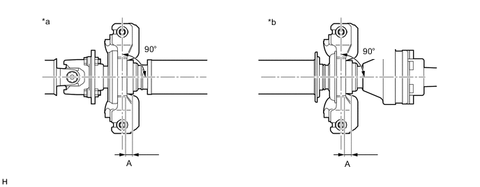
*a No. 2 Center Support Bearing Assembly (for Front Side) *b No. 2 Center Support Bearing Assembly (for Rear Side) Distance (A) 11.5 to 13.5 mm (0.453 to 0.531 in.) -
Fully tighten the 4 bolts.
- Torque:
- 36.8 N*m { 375 kgf*cm, 27 ft.*lbf }
-
Check that the center line of the bracket is at a right angle to the shaft axial direction.
-
-
INSPECT AND ADJUST TRANSFER OIL
-
INSPECT AND ADJUST JOINT ANGLE
Note
Measure the joint angle when the vehicle is raised using a four-post lift or when using a pit.
Tech Tips
If any vibration or noise occurs, perform the joint angle check as follows and replace the No. 2 center support bearing washer with a proper one.
-
Stabilize the propeller shaft and differential.
-
Turn the propeller shaft several times by hand to stabilize the center support bearings.
-
Using a jack, raise and lower the differential to stabilize the differential mounting cushion.
-
-
Check the No. 1 and No. 4 joint angles.
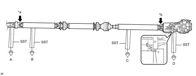
*a No. 1 Joint Angle *b No. 4 Joint Angle
-
Using SST, measure the transfer assembly installation angle (A) and propeller shaft assembly installation angle (B).
- SST
- 09370-50010
No. 1 Joint Angle Measurement Position No. 1 Joint Angle A-B -3.02° to -1.02° -
Using SST, measure the rear propeller shaft assembly installation angle (C) and rear differential carrier assembly installation angle (D).
- SST
- 09370-50010
No. 4 Joint Angle Measurement Position No. 4 Joint Angle C-D 0.71° to 2.71° If the measured angle is not within the specified range, adjust it with No. 2 center support bearing washer.
-
-
Adjust the No. 1 joint angle and No. 4 joint angle.
-
Select No. 2 center support bearing washers for adjustment.
No. 2 Center Support Bearing Washer Thickness Part No. Thickness mm (in.) 90201-10095 3.2 mm (0.126 in.) 90201-10081 4.5 mm (0.177 in.) 90201-10083 6.5 mm (0.256 in.) 90201-10084 9.0 mm (0.354 in.) 90201-10085 11.0 mm (0.433 in.) 90201-10086 13.5 mm (0.531 in.) 90201-10134 15.5 mm (0.610 in.) 90201-10135 17.5 mm (0.689 in.) Note
-
Make sure to use a No. 2 center support bearing washers of the same thickness on both the right and left sides.
-
Do not use 2 or more washers on a bolt.
-
-
-
-
INSTALL NO. 2 ENGINE UNDER COVER