FRONT DRIVE SHAFT ASSEMBLY(for 2GR-FKS) REMOVAL

CAUTION / NOTICE / HINT
Tech Tips
-
Use the same procedure for the RH side and LH side.
-
The procedure listed below is for the LH side.
PROCEDURE
-
REMOVE FRONT WHEELS
-
REMOVE NO. 1 ENGINE UNDER COVER
-
REMOVE FRONT FENDER APRON SEAL LH
-
REMOVE FRONT FENDER APRON SEAL RH (for AWD)
-
DRAIN AUTOMATIC TRANSAXLE FLUID
for UA80E: Click here
for UA80F: Click here
-
DRAIN TRANSFER OIL (for AWD)
-
REMOVE FRONT AXLE SHAFT NUT
-
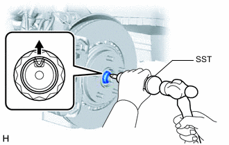
Using SST and a hammer, release the staked part of the front axle shaft nut.
- SST
- 09930-00010
Note
Loosen the staked part of the front axle shaft nut completely, otherwise the threads of the drive shaft may be damaged.
-
While applying the brakes, remove the front axle shaft nut.
-
-
SEPARATE FRONT SPEED SENSOR
-
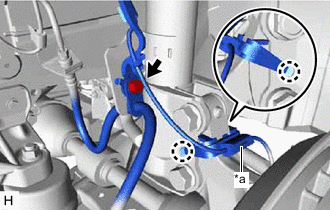
*a Sensor Clamp Disengage the 2 claws and separate the sensor clamp.
-
Remove the bolt and separate the front speed sensor and front flexible hose from the front shock absorber assembly.
Note
Be sure to separate the front speed sensor from the front shock absorber assembly completely.
-
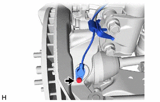
Remove the bolt and separate the front speed sensor from the steering knuckle.
Note
-
Prevent foreign matter from contacting the sensor tip.
-
Be careful not to damage the front speed sensor.
-
Clean the speed sensor installation hole and the contact surfaces every time the front speed sensor is removed.
-
-
-
SEPARATE TIE ROD ASSEMBLY
for 2WD: Click here
for AWD: Click here
-
SEPARATE FRONT STABILIZER LINK ASSEMBLY
-
SEPARATE FRONT LOWER NO. 1 SUSPENSION ARM SUB-ASSEMBLY
-
SEPARATE FRONT DRIVE SHAFT ASSEMBLY
-
REMOVE FRONT DRIVE SHAFT ASSEMBLY LH
-
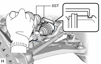
Using SST, remove the front drive shaft assembly LH.
- SST
- 09520-01010
- 09520-24010 ( 09520-32040 )
Note
-
Do not damage the front drive shaft oil seal LH.
-
Do not damage the front axle inboard joint boot.
-
Do not drop the front drive shaft assembly LH.
-
-
REMOVE FRONT DRIVE SHAFT ASSEMBLY RH (for 2WD)
-
Remove the 2 bolts and pull out the drive shaft together with the drive shaft bearing case sub-assembly.
-
Remove the front drive shaft assembly RH from the drive shaft bearing bracket.
Note
-
Do not damage the front drive shaft oil seal RH.
-
Do not damage the front axle inboard joint boot.
-
Do not drop the front drive shaft assembly RH.
Tech Tips
If it is difficult to disengage the fitting, tap the end of the front drive inboard joint assembly with a brass bar and a hammer.
-
-
-
REMOVE ENGINE MOUNTING BRACKET RH (for AWD)
-
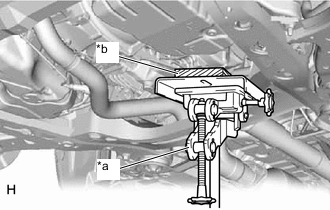
*a Transmission Jack *b Wooden Block Using a transmission jack and a wooden block, support the engine assembly with transaxle at the position shown in the illustration.
Note
-
Do not position the wooden block under the oil pan.
-
Do not damage the components surrounding the engine assembly with transaxle.
-
Do not damage the front drive shaft assembly.
-
Tilt the engine assembly with transaxle as little as possible.
-
Ensure that the transmission jack and wooden block are stable.
-
Keep supporting the engine assembly with transaxle with a transmission jack until the installation of the engine mounting insulator RH has been completed.
-
-
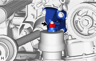
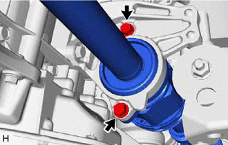
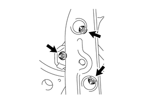
Remove the nut.
-
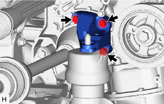
Remove the 3 bolts and engine mounting bracket RH from the engine assembly.
-
-
REMOVE ENGINE MOUNTING INSULATOR RH (for AWD)
-
Remove the 2 hole plugs.
-
Remove the 3 nuts and engine mounting insulator RH.
-
-
REMOVE FRONT DRIVE SHAFT ASSEMBLY RH (for AWD)
-
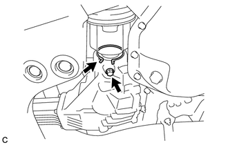
Separate the bearing bracket hole snap ring from the transfer assembly.
-
Remove the No. 1 drive shaft bearing bracket setting bolt and front drive shaft assembly RH from the transfer assembly.
Note
-
Do not damage the transfer case oil seal RH.
-
Do not damage the front axle inboard joint boot.
-
Do not drop the front drive shaft assembly RH.
-
-
Remove the bearing bracket hole snap ring from the front drive shaft assembly RH.
-
-
REMOVE FRONT DRIVE SHAFT HOLE SNAP RING (for LH Side)
-
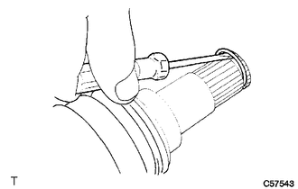
Using a screwdriver, remove the front drive shaft hole snap ring.
-