FRONT DRIVE SHAFT ASSEMBLY(for 1AR-FE) INSTALLATION

CAUTION / NOTICE / HINT
Tech Tips
-
Use the same procedure for the RH side and LH side.
-
The procedure listed below is for the LH side.
PROCEDURE
-
INSTALL FRONT DRIVE SHAFT HOLE SNAP RING (for LH Side)
-
Install a new front drive shaft hole snap ring.
Note
Face the end gap of the front drive shaft hole snap ring downward.
-
-
INSTALL FRONT DRIVE SHAFT ASSEMBLY LH
-
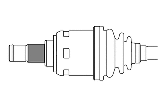

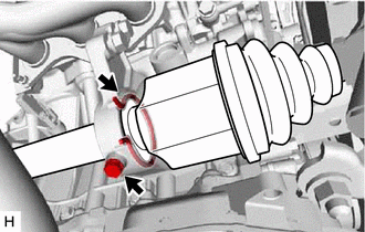
ATF WS Apply ATF WS to the area shown in the illustration.
-
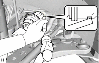
Align the inboard joint splines, and using a brass bar and a hammer, install the front drive shaft assembly LH.
Note
-
Face the end gap of the front drive shaft hole snap ring downward.
-
Do not damage the front drive shaft oil seal LH.
-
Do not damage the front axle inboard joint boot.
-
Make sure to center the front drive shaft assembly LH during installation to prevent damage to the front drive shaft hole snap ring.
Tech Tips
Confirm whether the drive shaft is securely driven in by checking the reaction force and sound.
-
-
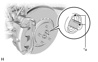
*a Matchmark Align the matchmarks and install the front drive shaft assembly LH to the front axle hub sub-assembly.
Note
-
Do not push the front axle assembly further out of the vehicle than is necessary.
-
Be careful not to damage the front axle outboard joint boot.
-
Check for any foreign matter on the speed sensor rotor and insertion part.
-
Do not damage the speed sensor rotor.
-
-
-
INSTALL FRONT DRIVE SHAFT ASSEMBLY RH
-
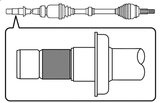
ATF WS Apply ATF WS to the area shown in the illustration.
-
Install a new bearing bracket hole snap ring to the front drive shaft assembly RH.
-
Install the front drive shaft assembly RH.
Note
-
Do not damage the front drive shaft oil seal RH.
-
Do not damage the front axle inboard joint boot.
-
When inserting the front drive shaft assembly RH, keep it level.
-
-
Install the bearing bracket hole snap ring and a new No. 1 drive shaft bearing bracket setting bolt.
- Torque:
- 32.4 N*m { 330 kgf*cm, 24 ft.*lbf }
-
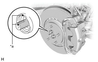
*a Matchmark Align the matchmarks and install the front drive shaft assembly RH to the front axle hub sub-assembly.
Note
-
Do not push the front axle assembly further out of the vehicle than is necessary.
-
Be careful not to damage the front axle outboard joint boot.
-
Check for any foreign matter on the speed sensor rotor and insertion part.
-
Do not damage the speed sensor rotor.
-
-
-
CONNECT FRONT LOWER NO. 1 SUSPENSION ARM SUB-ASSEMBLY
-
INSTALL FRONT STABILIZER LINK ASSEMBLY
-
CONNECT TIE ROD ASSEMBLY
-
INSTALL FRONT SPEED SENSOR
-
Install the front speed sensor to the steering knuckle with the bolt.
- Torque:
- 8.5 N*m { 87 kgf*cm, 75 in.*lbf }
Note
Do not twist the front speed sensor when installing it.
-
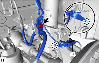
*a Sensor Clamp Install the front speed sensor and front flexible hose to the front shock absorber assembly with the bolt.
- Torque:
- 18.8 N*m { 192 kgf*cm, 14 ft.*lbf }
Note
Do not twist the front speed sensor and front flexible hose when installing them.
Tech Tips
Install the front speed sensor harness bracket first and then the front flexible hose.
-
Engage the 2 claws to install the sensor clamp.
-
-
INSTALL FRONT AXLE SHAFT NUT
-
Clean the threaded parts on the front drive shaft assembly and a new front axle shaft nut using non-residue solvent.
Note
-
Be sure to perform this work even when using a new front drive shaft assembly.
-
Keep the threaded parts free of oil and foreign matter.
-
-
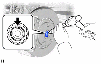
Using a 30 mm socket wrench, install the front axle shaft nut.
- Torque:
- 294 N*m { 2998 kgf*cm, 217 ft.*lbf }
Tech Tips
Keep depressing the brake pedal to prevent the drive shaft from rotating.
-
Using a chisel and a hammer, stake the front axle shaft nut.
-
-
ADD AUTOMATIC TRANSAXLE FLUID
-
INSTALL FRONT WHEELS
- Torque:
- 103 N*m { 1050 kgf*cm, 76 ft.*lbf }
-
INSPECT AND ADJUST FRONT WHEEL ALIGNMENT
-
CHECK FOR SPEED SENSOR SIGNAL