SEAT MEMORY SWITCH INSPECTION
PROCEDURE
-
INSPECT SEAT MEMORY SWITCH (DRIVER DOOR)
-
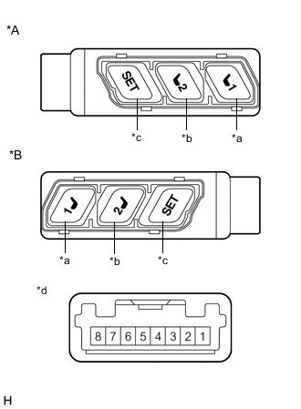
*A for LHD *B for RHD *a M1 Switch *b M2 Switch *c SET Switch *d Component without harness connected
(Seat Memory Switch (Driver Door))
Check the seat memory switch (driver door).
-
Measure the resistance according to the value(s) in the table below.
Standard Resistance Tester Connection Condition Specified Condition 4 - 2 M1 switch pressed Below 1 Ω M1 switch not pressed 10 kΩ or higher 3 - 2 M2 switch pressed Below 1 Ω M2 switch not pressed 10 kΩ or higher 8 - 2 SET switch pressed Below 1 Ω SET switch not pressed 10 kΩ or higher If the result is not as specified, replace the seat memory switch (driver door).
-
-
Check that the switch illumination comes on.
-
Apply battery voltage to the seat memory switch (driver door) and check that the switch illumination comes on.
OK Battery Connection Condition Specified Condition Battery positive (+) → 5
Battery negative (-) → 7
Always Switch illumination comes on If the result is not as specified, replace the seat memory switch (driver door).
-
-