METER / GAUGE SYSTEM Meter Illumination is Always Dark
DESCRIPTION
The combination meter assembly receives signals from this circuit to adjust the illumination of the combination meter assembly. The combination meter assembly sets the illumination level based on the user operation of the light control switch knob (combination meter assembly).
WIRING DIAGRAM
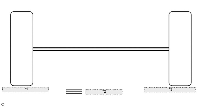
| *1 | Main Body ECU (Multiplex Network Body ECU) |
| *2 | CAN Communication Line |
| *3 | Combination Meter Assembly (Meter Circuit Plate) |
CAUTION / NOTICE / HINT
Note
-
If the main body ECU (multiplex network body ECU) is replaced, refer to Service Bulletin.*1
-
As the door control battery is installed between the vehicle battery and main body ECU (multiplex network body ECU), first perform the inspections in On-Vehicle Inspection to confirm that there are no malfunctions in the power source circuit for the main body ECU (multiplex network body ECU) before performing this troubleshooting procedure.*2
-
*1: w/ Smart Entry and Start System
-
*2: for LHD
Tech Tips
-
The meter illumination dims when the taillights are turned on.
-
Setting the meter illumination to maximum brightness cancels the above dimming of the meter illumination.
-
Setting the meter illumination to minimum brightness turns off the meter illumination.
-
Before starting the following inspection, check if Lighting System DTCs are output.
PROCEDURE
-
CHECK CAN COMMUNICATION SYSTEM
-
Check if CAN communication DTCs are output.
Result Result Proceed to CAN communication DTCs are not output. A CAN communication DTCs are output. B
B 
GO TO CAN COMMUNICATION SYSTEM Click here
A 
-
-
READ VALUE USING GTS (LIGHT SENSOR ILLUMINANCE)
-
Connect the GTS to the DLC3.
-
Turn the ignition switch to ON.
-
Turn the GTS on.
-
Enter the following menus: Body Electrical / Main Body / Data List.
-
Check the values by referring to the table below.
Body Electrical > Main Body > Data ListTester Display Measurement Item Range Normal Condition Diagnostic Note Light Sensor Illuminance Light sensor illuminance 0 to 8191 lx Value is output according to ambient light level -
Body Electrical > Main Body > Data ListTester Display Light Sensor Illuminance Result Result Proceed to The output value changes according to the ambient light level. A The output value does not change according to the ambient light level. B
B
CHECK CUSTOMIZE PARAMETER SETTING (SENSITIVITY) Click here
A
-
-
REPLACE MAIN BODY ECU (MULTIPLEX NETWORK BODY ECU) (MULTIPLEX NETWORK BODY ECU)
-
Replace the main body ECU (multiplex network body ECU) with a new or known good one.
OK The operation of the combination meter assembly returns to normal. Result Proceed to OK NG
OK
END
NG
REPLACE COMBINATION METER ASSEMBLY Click here
-