METER / GAUGE SYSTEM, Diagnostic DTC:B1500
| DTC Code | DTC Name |
|---|---|
| B1500 | Fuel Sender Open Detected |
DESCRIPTION
This DTC is stored when the combination meter assembly detects a fuel sender gauge assembly malfunction via a direct line.
| DTC No. | Detection Item | DTC Detection Condition | Trouble Area | Memory | Note |
|---|---|---|---|---|---|
| B1500 | Fuel Sender Open Detected | Diagnosis Condition
Malfunction Status (for 1AR-FE):
Malfunction Status (for 2GR-FKS):
|
|
- | - |
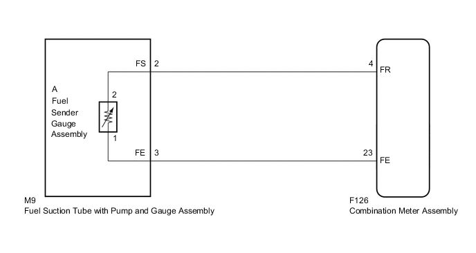
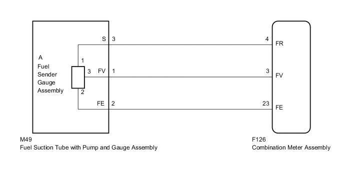
WIRING DIAGRAM
-
for 1AR-FE
-
for 2GR-FKS
PROCEDURE
-
READ VALUE USING GTS (FUEL INPUT)
-
Connect the GTS to the DLC3.
-
Turn the ignition switch to ON.
-
Turn the GTS on.
-
Enter the following menus: Body Electrical / Combination Meter / Data List.
-
Read the Data List according to the display on the GTS.
Body Electrical > Combination Meter > Data ListTester Display Measurement Item Range Normal Condition Diagnostic Note Fuel Input Fuel input Min.: 0 L, Max.: 172.5 L Fuel receiver gauge indicates F: 64.8 L
Fuel receiver gauge indicates 3/4: 51.6 L
Fuel receiver gauge indicates 1/2: 36.0 L
Fuel receiver gauge indicates 1/4: 20.4 L
Fuel receiver gauge indicates E: 7.2 L
Unit: Liter
Body Electrical > Combination Meter > Data ListTester Display Fuel Input Result Result Proceed to Fuel level data can be displayed on the GTS and DTC B1500 is output A Fuel level data cannot be displayed on the GTS B
A 
REPLACE COMBINATION METER ASSEMBLY Click here
B 
-
-
CONFIRM MODEL
-
Choose the model to be inspected.
Result Result Proceed to for 1AR-FE A for 2GR-FKS B
B 
INSPECT FUEL SENDER GAUGE ASSEMBLY (POWER SOURCE) Click here
A
-
-
INSPECT FUEL SENDER GAUGE ASSEMBLY
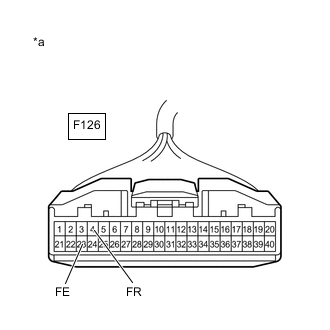
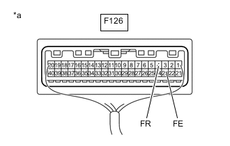
*a Front view of wire harness connector
(to Combination Meter Assembly)
-
Disconnect the F126 combination meter assembly connector.
-
Measure the resistance according to the value(s) in the table below.
Standard Resistance Tester Connection Condition Specified Condition F126-4 (FR) - F126-23 (FE) Always 13.5 to 414.5 Ω Result Proceed to OK NG
OK
REPLACE COMBINATION METER ASSEMBLY Click here
NG
-
-
CHECK HARNESS AND CONNECTOR (FUEL SUCTION TUBE WITH PUMP AND GAUGE ASSEMBLY - COMBINATION METER ASSEMBLY)
-
Disconnect the M9 fuel suction tube with pump and gauge assembly connector.
-
Measure the resistance according to the value(s) in the table below.
Standard Resistance Tester Connection Condition Specified Condition M9-2 (FS) - F126-4 (FR) Always Below 1 Ω M9-3 (FE) - F126-23 (FE) Always Below 1 Ω M9-2 (FS) or F126-4 (FR) - Body ground Always 10 kΩ or higher M9-3 (FE) or F126-23 (FE) - Body ground Always 10 kΩ or higher Result Proceed to OK NG
NG
REPAIR OR REPLACE HARNESS OR CONNECTOR
OK
-
-
INSPECT FUEL SENDER GAUGE ASSEMBLY
-
Remove the fuel sender gauge assembly.
-
Inspect the fuel sender gauge assembly.
OK Fuel sender gauge assembly is normal. Result Proceed to OK NG
NG
REPLACE FUEL SENDER GAUGE ASSEMBLY Click here
OK
-
-
INSPECT FUEL SUCTION TUBE WITH PUMP AND GAUGE ASSEMBLY
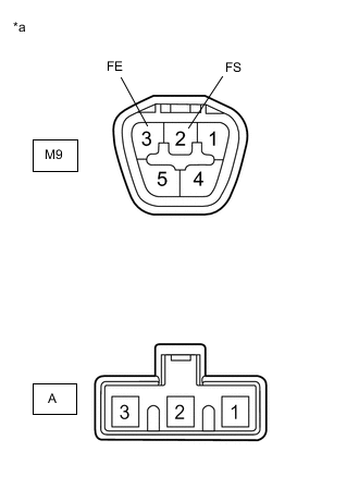
*a Component without harness connected
(Fuel Suction Tube with Pump and Gauge Assembly)
-
Measure the resistance according to the value(s) in the table below.
Standard Resistance Tester Connection Condition Specified Condition M9-2 (FS) - A-2 Always Below 1 Ω M9-3 (FE) - A-1 Always Below 1 Ω Result Proceed to OK NG
OK
REPLACE COMBINATION METER ASSEMBLY Click here
NG
REPLACE FUEL SUCTION TUBE WITH PUMP AND GAUGE ASSEMBLY Click here
-
-
INSPECT FUEL SENDER GAUGE ASSEMBLY (POWER SOURCE)
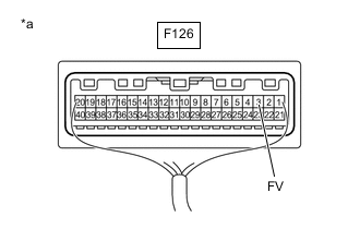
*a Component with harness connected
(Combination Meter Assembly (Meter Circuit Plate))
-
Measure the voltage according to the value(s) in the table below.
Standard Voltage Tester Connection Condition Specified Condition F126-3 (FV) - Body ground Ignition switch ON 4.5 to 5.5 V Result Proceed to OK NG
NG
REPLACE COMBINATION METER ASSEMBLY Click here
OK
-
-
INSPECT FUEL SENDER GAUGE ASSEMBLY
*a Component with harness connected
(Combination Meter Assembly)
-
Measure the voltage according to the value(s) in the table below.
Standard Voltage Tester Connection Condition Specified Condition F126-4 (FR) - F126-23 (FE) Ignition switch ON 0.5 to 4.4 V Result Proceed to OK NG
OK
REPLACE COMBINATION METER ASSEMBLY Click here
NG
-
-
CHECK HARNESS AND CONNECTOR (FUEL SUCTION TUBE WITH PUMP AND GAUGE ASSEMBLY - COMBINATION METER ASSEMBLY)
-
Disconnect the F126 combination meter assembly connector.
-
Disconnect the M49 fuel suction tube with pump and gauge assembly connector.
-
Measure the resistance according to the value(s) in the table below.
Standard Resistance Tester Connection Condition Specified Condition M49-3 (S) - F126-4 (FR) Always Below 1 Ω M49-2 (FE) - F126-23 (FE) Always Below 1 Ω M49-1 (FV) - F126-3 (FV) Always Below 1 Ω M49-3 (S) or F126-4 (FR) - Body ground Always 10 kΩ or higher M49-2 (FE) or F126-23 (FE) - Body ground Always 10 kΩ or higher M49-1 (FV) or F126-3 (FV) - Body ground Always 10 kΩ or higher Result Proceed to OK NG
NG
REPAIR OR REPLACE HARNESS OR CONNECTOR
OK
-
-
INSPECT FUEL SENDER GAUGE ASSEMBLY
-
Remove the fuel sender gauge assembly.
-
Inspect the fuel sender gauge assembly.
OK Fuel sender gauge assembly is normal. Result Proceed to OK NG
NG
REPLACE FUEL SENDER GAUGE ASSEMBLY Click here
OK
-
-
INSPECT FUEL SUCTION TUBE WITH PUMP AND GAUGE ASSEMBLY
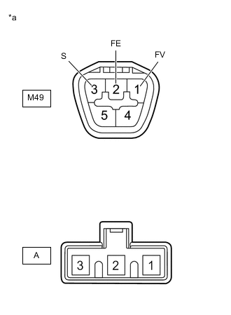
*a Component without harness connected
(Fuel Suction Tube with Pump and Gauge Assembly)
-
Measure the resistance according to the value(s) in the table below.
Standard Resistance Tester Connection Condition Specified Condition M49-1 (FV) - A-3 Always Below 1 Ω M49-2 (FE) - A-2 Always Below 1 Ω M49-3 (S) - A-1 Always Below 1 Ω Result Proceed to OK NG
OK
REPLACE COMBINATION METER ASSEMBLY Click here
NG
REPLACE FUEL SUCTION TUBE WITH PUMP AND GAUGE ASSEMBLY Click here
-