METER / GAUGE SYSTEM, Diagnostic DTC:B1507, B1508
| DTC Code | DTC Name |
|---|---|
| B1507 | Open in Turn Signal Circuit |
| B1508 | Short in Turn Signal / Hazard Flasher Circuit |
DESCRIPTION
These DTCs are stored when the combination meter assembly detects an open in a turn signal light circuit, or a short in a turn signal light circuit or the hazard warning light circuit.
| DTC No. | Detection Item | DTC Detection Condition | Trouble Area | Memory | Note |
|---|---|---|---|---|---|
| B1507 | Open in Turn Signal Circuit | When IG voltage is 9.5 V or more and the following condition is detected:
|
|
DTC stored | - |
| B1508 | Short in Turn Signal / Hazard Flasher Circuit | When IG voltage is 9.5 V or more and the following condition is detected:
|
|
DTC stored | - |
-
*1: w/ Seat Position Memory
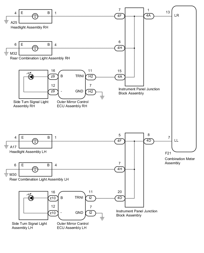
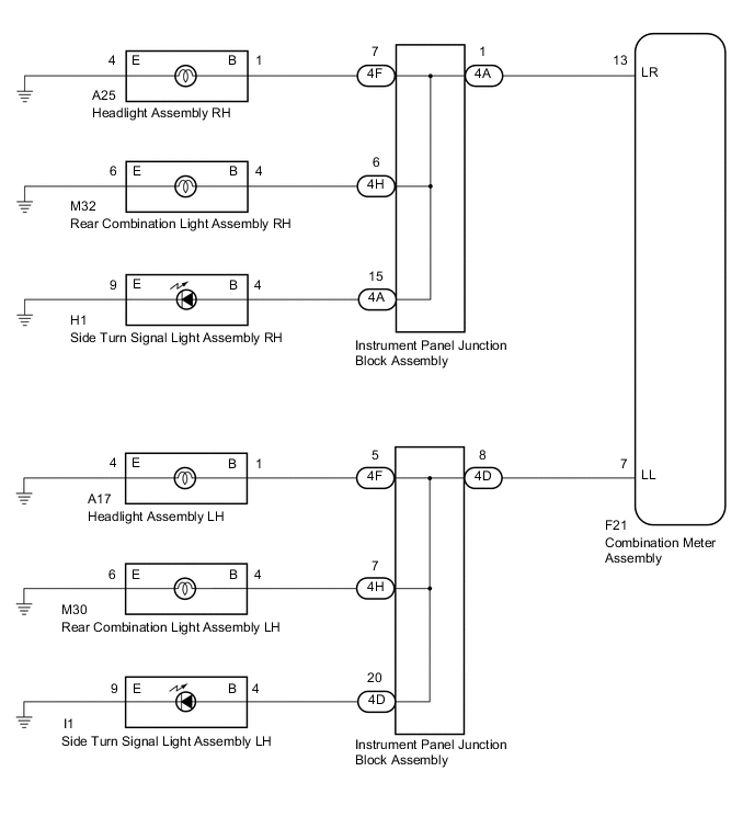
WIRING DIAGRAM
-
w/ Seat Position Memory
-
w/o Seat Position Memory
CAUTION / NOTICE / HINT
Note
Inspect the LEDs and bulbs for this system before performing the following procedure.
PROCEDURE
-
INSPECT LIGHTS
-
Inspect the illumination of each turn signal light.
Result Result Proceed to All RH turn signal lights or all LH turn signal lights do not blink. A RH side turn signal light does not illuminate. B LH side turn signal light does not illuminate. C
B 
CHECK TURN SIGNAL LIGHTS (RH SIDE) Click here
C
CHECK TURN SIGNAL LIGHTS (LH SIDE) Click here
A 
-
-
CHECK HARNESS AND CONNECTOR (COMBINATION METER ASSEMBLY - INSTRUMENT PANEL JUNCTION BLOCK ASSEMBLY OR BODY GROUND)
-
Disconnect the F21 combination meter assembly connector.
-
RH side
-
Disconnect the 4A instrument panel junction block assembly connector.
-
Measure the resistance according to the value(s) in the table below.
Standard Resistance (Check for Open) Tester Connection Condition Specified Condition F21-13 (LR) - 4A-1 Always Below 1 Ω Standard Resistance (Check for Short) Tester Connection Condition Specified Condition F21-13 (LR) - Body ground Always 10 kΩ or higher
-
-
LH side
-
Disconnect the 4D instrument panel junction block assembly connector.
-
Measure the resistance according to the value(s) in the table below.
Standard Resistance (Check for Open) Tester Connection Condition Specified Condition F21-7 (LL) - 4D-8 Always Below 1 Ω Standard Resistance (Check for Short) Tester Connection Condition Specified Condition F21-7 (LL) - Body ground Always 10 kΩ or higher
Result Proceed to OK NG -
NG 
REPAIR OR REPLACE HARNESS OR CONNECTOR
OK
-
-
INSPECT INSTRUMENT PANEL JUNCTION BLOCK ASSEMBLY
-
Remove the instrument panel junction block assembly.
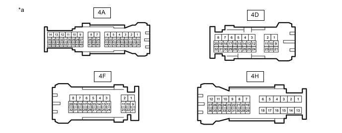
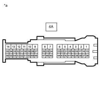
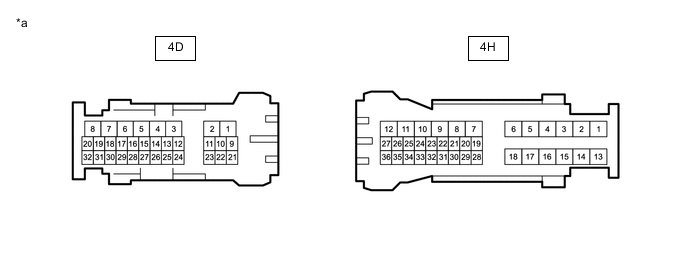
*a Component without harness connected
(Instrument Panel Junction Block Assembly)
- - -
RH side
-
Measure the resistance according to the value(s) in the table below.
Standard Resistance Tester Connection Condition Specified Condition 4A-1 - 4F-7 Always Below 1 Ω 4A-1 - 4H-6 Always Below 1 Ω 4A-1 - 4A-15 Always Below 1 Ω
-
-
LH side
-
Measure the resistance according to the value(s) in the table below.
Standard Resistance Tester Connection Condition Specified Condition 4D-8 - 4F-5 Always Below 1 Ω 4D-8 - 4H-7 Always Below 1 Ω 4D-8 - 4D-20 Always Below 1 Ω
Result Proceed to OK NG -
OK
REPLACE COMBINATION METER ASSEMBLY Click here
NG
REPLACE INSTRUMENT PANEL JUNCTION BLOCK ASSEMBLY Click here
-
-
CHECK TURN SIGNAL LIGHTS (RH SIDE)
-
Turn the ignition switch to ON.
-
Set the headlight dimmer switch assembly to the right turn switch position.
-
Check the operation of the turn signal lights.
Result Result Proceed to Front turn signal light assembly does not blink. A Side turn signal light assembly does not blink. B Rear turn signal light assembly does not blink. C
B
CONFIRM VEHICLE TYPE Click here
C
CHECK HARNESS AND CONNECTOR (REAR COMBINATION LIGHT ASSEMBLY RH - INSTRUMENT PANEL JUNCTION BLOCK ASSEMBLY OR BODY GROUND) Click here
A
-
-
CHECK HARNESS AND CONNECTOR (HEADLIGHT ASSEMBLY RH - INSTRUMENT PANEL JUNCTION BLOCK ASSEMBLY OR BODY GROUND)
-
Disconnect the A25 headlight assembly RH connector.
-
Disconnect the 4F instrument panel junction block assembly connector.
-
Measure the resistance according to the value(s) in the table below.
Standard Resistance (Check for Open) Tester Connection Condition Specified Condition A25-1 (B) - 4F-7 Always Below 1 Ω A25-4 (E) - Body ground Always Below 1 Ω Standard Resistance (Check for Short) Tester Connection Condition Specified Condition 4F-7 - Body ground Always 10 kΩ or higher Result Proceed to OK NG
NG
REPAIR OR REPLACE HARNESS OR CONNECTOR
OK
-
-
INSPECT INSTRUMENT PANEL JUNCTION BLOCK ASSEMBLY
-
Remove the instrument panel junction block assembly.
-
Measure the resistance according to the value(s) in the table below.
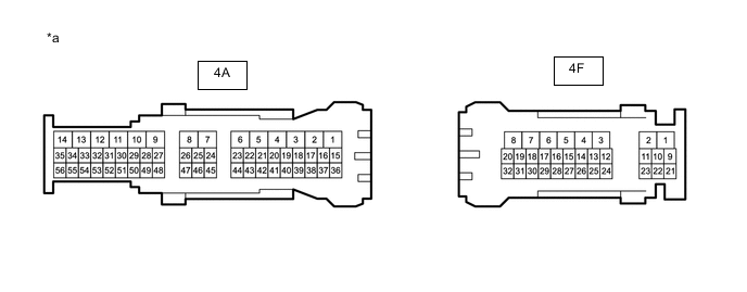
*a Component without harness connected
(Instrument Panel Junction Block Assembly)
- - Standard Resistance Tester Connection Condition Specified Condition 4A-1 - 4F-7 Always Below 1 Ω Result Proceed to OK NG
OK
REPLACE COMBINATION METER ASSEMBLY Click here
NG
REPLACE INSTRUMENT PANEL JUNCTION BLOCK ASSEMBLY Click here
-
-
CONFIRM VEHICLE TYPE
-
Confirm the vehicle type.
Result Result Proceed to w/ Seat Position Memory A w/o Seat Position Memory B
B
CHECK HARNESS AND CONNECTOR (SIDE TURN SIGNAL LIGHT ASSEMBLY RH - INSTRUMENT PANEL JUNCTION BLOCK ASSEMBLY OR BODY GROUND) Click here
A
-
-
CHECK HARNESS AND CONNECTOR (OUTER MIRROR CONTROL ECU ASSEMBLY RH - INSTRUMENT PANEL JUNCTION BLOCK ASSEMBLY OR BODY GROUND)
-
Disconnect the H2 outer mirror control ECU assembly RH connector.
-
Disconnect the 4A instrument panel junction block assembly connector.
-
Measure the resistance according to the value(s) in the table below.
Standard Resistance (Check for Open) Tester Connection Condition Specified Condition H2-11 (TRNI) - 4A-15 Always Below 1 Ω H2-7 (GND) - Body ground Always Below 1 Ω Standard Resistance (Check for Short) Tester Connection Condition Specified Condition 4A-15 - Body ground Always 10 kΩ or higher Result Proceed to OK NG
NG
REPAIR OR REPLACE HARNESS OR CONNECTOR
OK
-
-
INSPECT INSTRUMENT PANEL JUNCTION BLOCK ASSEMBLY
-
Remove the instrument panel junction block assembly.
-
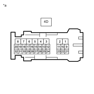
*a Component without harness connected
(Instrument Panel Junction Block Assembly)
Measure the resistance according to the value(s) in the table below.
Standard Resistance Tester Connection Condition Specified Condition 4A-1 - 4A-15 Always Below 1 Ω Result Proceed to OK NG
NG
REPLACE INSTRUMENT PANEL JUNCTION BLOCK ASSEMBLY Click here
OK
-
-
REPLACE OUTER MIRROR CONTROL ECU ASSEMBLY RH
-
Replace the outer mirror control ECU assembly RH with a new or known good one.
-
Check for the DTCs.
Body Electrical > Combination Meter > Trouble CodesResult Result Proceed to DTCs are output. A DTCs are not output. B
A
REPLACE COMBINATION METER ASSEMBLY Click here
B
END
-
-
CHECK HARNESS AND CONNECTOR (SIDE TURN SIGNAL LIGHT ASSEMBLY RH - INSTRUMENT PANEL JUNCTION BLOCK ASSEMBLY OR BODY GROUND)
-
Disconnect the H1 side turn signal light assembly RH connector.
-
Disconnect the 4A instrument panel junction block assembly connector.
-
Measure the resistance according to the value(s) in the table below.
Standard Resistance (Check for Open) Tester Connection Condition Specified Condition H1-4 (B) - 4A-15 Always Below 1 Ω H1-9 (E) - Body ground Always Below 1 Ω Standard Resistance (Check for Short) Tester Connection Condition Specified Condition 4A-15 - Body ground Always 10 kΩ or higher Result Proceed to OK NG
NG
REPAIR OR REPLACE HARNESS OR CONNECTOR
OK
-
-
INSPECT INSTRUMENT PANEL JUNCTION BLOCK ASSEMBLY
-
Remove the instrument panel junction block assembly.
-
*a Component without harness connected
(Instrument Panel Junction Block Assembly)
Measure the resistance according to the value(s) in the table below.
Standard Resistance Tester Connection Condition Specified Condition 4A-1 - 4A-15 Always Below 1 Ω Result Proceed to OK NG
OK
REPLACE COMBINATION METER ASSEMBLY Click here
NG
REPLACE INSTRUMENT PANEL JUNCTION BLOCK ASSEMBLY Click here
-
-
CHECK HARNESS AND CONNECTOR (REAR COMBINATION LIGHT ASSEMBLY RH - INSTRUMENT PANEL JUNCTION BLOCK ASSEMBLY OR BODY GROUND)
-
Disconnect the M32 rear combination light assembly RH connector.
-
Disconnect the 4H instrument panel junction block assembly connector.
-
Measure the resistance according to the value(s) in the table below.
Standard Resistance (Check for Open) Tester Connection Condition Specified Condition M32-4 (B) - 4H-6 Always Below 1 Ω M32-6 (E) - Body ground Always Below 1 Ω Standard Resistance (Check for Short) Tester Connection Condition Specified Condition 4H-6 - Body ground Always 10 kΩ or higher Result Proceed to OK NG
NG
REPAIR OR REPLACE HARNESS OR CONNECTOR
OK
-
-
INSPECT INSTRUMENT PANEL JUNCTION BLOCK ASSEMBLY
-
Remove the instrument panel junction block assembly.
-
Measure the resistance according to the value(s) in the table below.
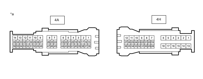
*a Component without harness connected
(Instrument Panel Junction Block Assembly)
- - Standard Resistance Tester Connection Condition Specified Condition 4A-1 - 4H-6 Always Below 1 Ω Result Proceed to OK NG
OK
REPLACE COMBINATION METER ASSEMBLY Click here
NG
REPLACE INSTRUMENT PANEL JUNCTION BLOCK ASSEMBLY Click here
-
-
CHECK TURN SIGNAL LIGHTS (LH SIDE)
-
Turn the ignition switch to ON.
-
Set the headlight dimmer switch assembly to the left turn switch position.
-
Check the operation of the turn signal lights.
Result Result Proceed to Front turn signal light assembly does not blink. A Side turn signal light assembly does not blink. B Rear turn signal light assembly does not blink. C
B
CONFIRM VEHICLE TYPE Click here
C
CHECK HARNESS AND CONNECTOR (REAR COMBINATION LIGHT ASSEMBLY LH - INSTRUMENT PANEL JUNCTION BLOCK ASSEMBLY OR BODY GROUND) Click here
A
-
-
CHECK HARNESS AND CONNECTOR (HEADLIGHT ASSEMBLY LH - INSTRUMENT PANEL JUNCTION BLOCK ASSEMBLY OR BODY GROUND)
-
Disconnect the A17 headlight assembly LH connector.
-
Disconnect the 4F instrument panel junction block assembly connector.
-
Measure the resistance according to the value(s) in the table below.
Standard Resistance (Check for Open) Tester Connection Condition Specified Condition A17-1 (B) - 4F-5 Always Below 1 Ω A17-4 (E) - Body ground Always Below 1 Ω Standard Resistance (Check for Short) Tester Connection Condition Specified Condition A17-1 (B) - Body ground Always 10 kΩ or higher Result Proceed to OK NG
NG
REPAIR OR REPLACE HARNESS OR CONNECTOR
OK
-
-
INSPECT INSTRUMENT PANEL JUNCTION BLOCK ASSEMBLY
-
Remove the instrument panel junction block assembly.
-
Measure the resistance according to the value(s) in the table below.
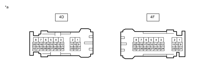
*a Component without harness connected
(Instrument Panel Junction Block Assembly)
- - Standard Resistance Tester Connection Condition Specified Condition 4D-8 - 4F-5 Always Below 1 Ω Result Proceed to OK NG
OK
REPLACE COMBINATION METER ASSEMBLY Click here
NG
REPLACE INSTRUMENT PANEL JUNCTION BLOCK ASSEMBLY Click here
-
-
CONFIRM VEHICLE TYPE
-
Confirm the vehicle type.
Result Result Proceed to w/ Seat Position Memory A w/o Seat Position Memory B
B
CHECK HARNESS AND CONNECTOR (SIDE TURN SIGNAL LIGHT ASSEMBLY LH - INSTRUMENT PANEL JUNCTION BLOCK ASSEMBLY OR BODY GROUND) Click here
A
-
-
CHECK HARNESS AND CONNECTOR (OUTER MIRROR CONTROL ECU ASSEMBLY LH - INSTRUMENT PANEL JUNCTION BLOCK ASSEMBLY OR BODY GROUND)
-
Disconnect the I2 outer mirror control ECU assembly LH connector.
-
Disconnect the 4D instrument panel junction block assembly connector.
-
Measure the resistance according to the value(s) in the table below.
Standard Resistance (Check for Open) Tester Connection Condition Specified Condition I2-11 (TRNI) - 4D-20 Always Below 1 Ω I2-7 (GND) - Body ground Always Below 1 Ω Standard Resistance (Check for Short) Tester Connection Condition Specified Condition 4D-20 - Body ground Always 10 kΩ or higher Result Proceed to OK NG
NG
REPAIR OR REPLACE HARNESS OR CONNECTOR
OK
-
-
INSPECT INSTRUMENT PANEL JUNCTION BLOCK ASSEMBLY
-
Remove the instrument panel junction block assembly.
-
*a Component without harness connected
(Instrument Panel Junction Block Assembly)
Measure the resistance according to the value(s) in the table below.
Standard Resistance Tester Connection Condition Specified Condition 4D-8 - 4D-20 Always Below 1 Ω Result Proceed to OK NG
NG
REPLACE INSTRUMENT PANEL JUNCTION BLOCK ASSEMBLY Click here
OK
-
-
REPLACE OUTER MIRROR CONTROL ECU ASSEMBLY LH
-
Replace the outer mirror control ECU assembly LH with a new or known good one.
-
Check for the DTCs.
Body Electrical > Combination Meter > Trouble CodesResult Result Proceed to DTCs are output. A DTCs are not output. B
A
REPLACE COMBINATION METER ASSEMBLY Click here
B
END
-
-
CHECK HARNESS AND CONNECTOR (SIDE TURN SIGNAL LIGHT ASSEMBLY LH - INSTRUMENT PANEL JUNCTION BLOCK ASSEMBLY OR BODY GROUND)
-
Disconnect the I1 side turn signal light assembly LH connector.
-
Disconnect the 4D instrument panel junction block assembly connector.
-
Measure the resistance according to the value(s) in the table below.
Standard Resistance (Check for Open) Tester Connection Condition Specified Condition I1-4 (B) - 4D-20 Always Below 1 Ω I1-9 (E) - Body ground Always Below 1 Ω Standard Resistance (Check for Short) Tester Connection Condition Specified Condition 4D-20 - Body ground Always 10 kΩ or higher Result Proceed to OK NG
NG
REPAIR OR REPLACE HARNESS OR CONNECTOR
OK
-
-
INSPECT INSTRUMENT PANEL JUNCTION BLOCK ASSEMBLY
-
Remove the instrument panel junction block assembly.
-
*a Component without harness connected
(Instrument Panel Junction Block Assembly)
Measure the resistance according to the value(s) in the table below.
Standard Resistance Tester Connection Condition Specified Condition 4D-8 - 4D-20 Always Below 1 Ω Result Proceed to OK NG
OK
REPLACE COMBINATION METER ASSEMBLY Click here
NG
REPLACE INSTRUMENT PANEL JUNCTION BLOCK ASSEMBLY Click here
-
-
CHECK HARNESS AND CONNECTOR (REAR COMBINATION LIGHT ASSEMBLY LH - INSTRUMENT PANEL JUNCTION BLOCK ASSEMBLY OR BODY GROUND)
-
Disconnect the M30 rear combination light assembly LH connector.
-
Disconnect the 4H instrument panel junction block assembly connector.
-
Measure the resistance according to the value(s) in the table below.
Standard Resistance (Check for Open) Tester Connection Condition Specified Condition M30-4 (B) - 4H-7 Always Below 1 Ω M30-6 (E) - Body ground Always Below 1 Ω Standard Resistance (Check for Short) Tester Connection Condition Specified Condition 4H-7 - Body ground Always 10 kΩ or higher Result Proceed to OK NG
NG
REPAIR OR REPLACE HARNESS OR CONNECTOR
OK
-
-
INSPECT INSTRUMENT PANEL JUNCTION BLOCK ASSEMBLY
-
Remove the instrument panel junction block assembly.
-
Measure the resistance according to the value(s) in the table below.
*a Component without harness connected
(Instrument Panel Junction Block Assembly)
- - Standard Resistance Tester Connection Condition Specified Condition 4D-8 - 4H-7 Always Below 1 Ω Result Proceed to OK NG
OK
REPLACE COMBINATION METER ASSEMBLY Click here
NG
REPLACE INSTRUMENT PANEL JUNCTION BLOCK ASSEMBLY Click here
-