LIGHTING SYSTEM Ambient Light Circuit
DESCRIPTION
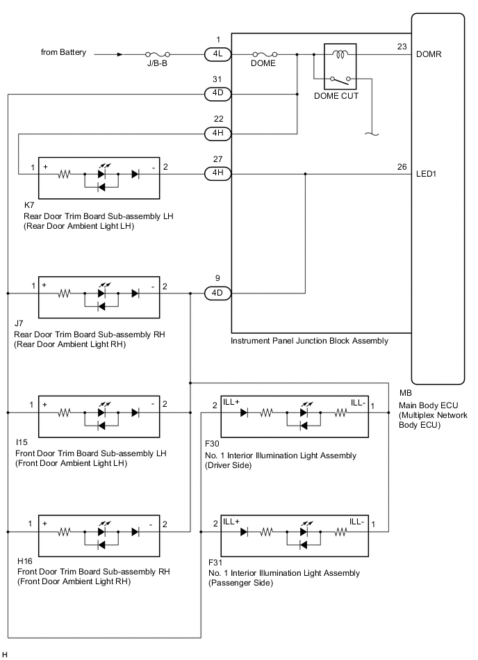
The main body ECU (multiplex network body ECU) controls the ambient lights.
WIRING DIAGRAM
CAUTION / NOTICE / HINT
Note
-
Inspect the fuses for circuits related to this system before performing the following procedure.
-
If the main body ECU (multiplex network body ECU) is replaced, refer to Service Bulletin.*1
-
As the door control battery is installed between the vehicle battery and main body ECU (multiplex network body ECU), first perform the inspections in On-Vehicle Inspection to confirm that there are no malfunctions in the power source circuit for the main body ECU (multiplex network body ECU) before performing this troubleshooting procedure.*2
-
*1: w/ Smart Entry and Start System
-
*2: for LHD
PROCEDURE
-
CONFIRM SYMPTOMS
-
Confirm problem symptoms.
Result Result Proceed to Ambient lights do not come on A Ambient light dimmer control does not operate B
B 
PERFORM ACTIVE TEST USING GTS Click here
A 
-
-
PERFORM ACTIVE TEST USING GTS
-
Connect the GTS to the DLC3.
-
Turn the ignition switch to ON.
-
Turn the GTS on.
-
Enter the following menus: Body Electrical / Main Body / Active Test.
-
Check that the ambient lights come on.
Body Electrical > Main Body > Active TestTester Display Measurement Item Control Range Diagnostic Note Interior Illumination Light1 Ambient lights ON or OFF Precondition for using the Active Test to turn lights on and off:
-
Ignition switch is turned off just before performing the Active Test.
Body Electrical > Main Body > Active TestTester Display Interior Illumination Light1 OK All ambient lights come on. Result Result Proceed to OK A NG (All ambient lights do not illuminate) B NG (Ambient light does not illuminate (for Front Door)) C NG (Ambient light does not illuminate (for Rear Door)) NG (Ambient light does not illuminate (for Instrument Panel Side)) -
A 
PROBLEM SYMPTOMS TABLE FOR EACH PROBLEM SYMPTOM Click here
C
GO TO PROBLEM SYMPTOMS TABLE FOR EACH PROBLEM SYMPTOM Click here
B
-
-
CHECK HARNESS AND CONNECTOR (POWER SOURCE - INSTRUMENT PANEL JUNCTION BLOCK ASSEMBLY)
-
Disconnect the 4L instrument panel junction block assembly connector.
-
Measure the voltage according to the value(s) in the table below.
Standard Voltage Tester Connection Condition Specified Condition 4L-1 - Body ground Always 11 to 14 V Result Proceed to OK NG
NG
REPAIR OR REPLACE HARNESS OR CONNECTOR
OK
-
-
INSPECT INSTRUMENT PANEL JUNCTION BLOCK ASSEMBLY
-
Remove the instrument panel junction block assembly.
-
Remove the main body ECU (multiplex network body ECU) from the instrument panel junction block assembly.
-
Measure the resistance according to the value(s) in the table below.
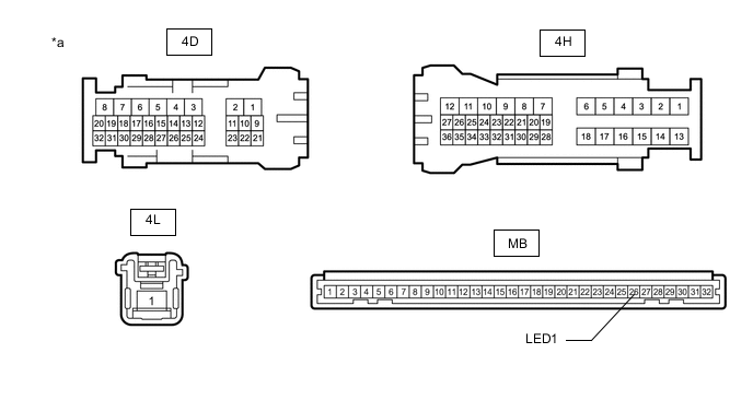
*a Component without harness connected
(Instrument Panel Junction Block Assembly)
- - Standard Resistance Tester Connection Condition Specified Condition 4L-1 - 4H-22 Always Below 1 Ω 4L-1 - 4D-31 Always Below 1 Ω 4H-27 - MB-26 (LED1) Always Below 1 Ω 4D-9 - MB-26 (LED1) Always Below 1 Ω Result Proceed to OK NG
OK
REPLACE MAIN BODY ECU (MULTIPLEX NETWORK BODY ECU) Click here
NG
REPLACE INSTRUMENT PANEL JUNCTION BLOCK ASSEMBLY Click here
-
-
PERFORM ACTIVE TEST USING GTS
-
Connect the GTS to the DLC3.
-
Turn the ignition switch to ON.
-
Turn the GTS on.
-
Enter the following menus: Body Electrical / Main Body / Active Test.
-
Check that the ambient lights come on.
Body Electrical > Main Body > Active TestTester Display Measurement Item Control Range Diagnostic Note Interior Illumination Light1 Ambient lights ON or OFF Preconditions for using the Active Test to check dimmer controlled illumination:
-
Engine running
-
Shift lever is in any position other than P.
Body Electrical > Main Body > Active TestTester Display Interior Illumination Light1 OK Ambient light dimmer control operates. Result Proceed to OK NG -
OK
PROCEED TO NEXT SUSPECTED AREA SHOWN IN PROBLEM SYMPTOMS TABLE Click here
NG
REPLACE MAIN BODY ECU (MULTIPLEX NETWORK BODY ECU) Click here
-