THEFT DETERRENT SYSTEM TERMINALS OF ECU
-
CHECK MAIN BODY ECU (MULTIPLEX NETWORK BODY ECU) AND INSTRUMENT PANEL JUNCTION BLOCK ASSEMBLY
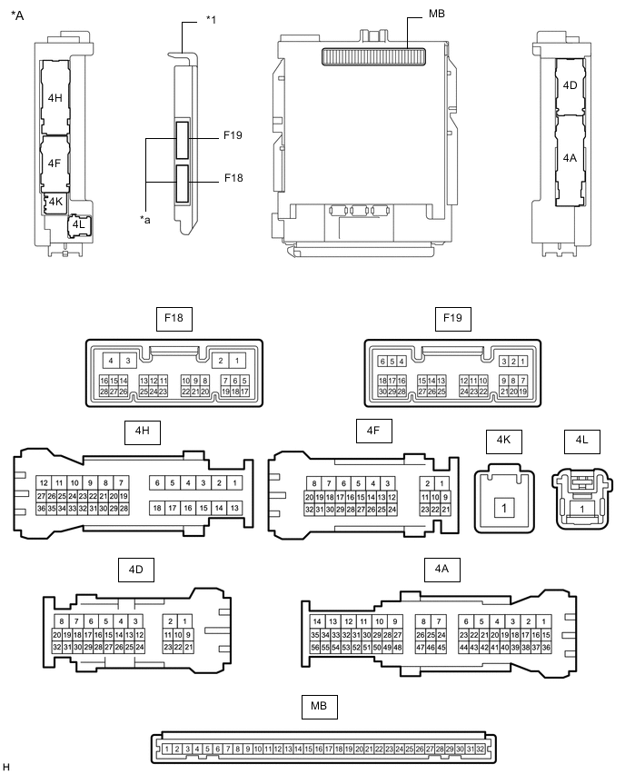
*A Main Body ECU (Multiplex Network Body ECU) with 2 Connectors - - *1 Main Body ECU (Multiplex Network Body ECU) - - *a 2 connectors - - 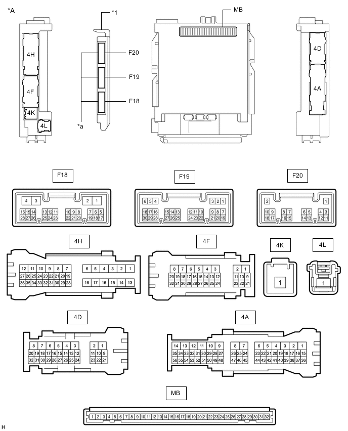
*A Main Body ECU (Multiplex Network Body ECU) with 3 Connectors - - *1 Main Body ECU (Multiplex Network Body ECU) - - *a 3 connectors - -
-
Remove the main body ECU (multiplex network body ECU) from instrument panel junction block assembly.
-
Reconnect the instrument panel junction block assembly connectors.
-
Measure the resistance and voltage according to the value(s) in the table below.
Tech Tips
Measure the values on the wire harness side with the connector disconnected.
Terminal No. (Symbol) Wiring Color Terminal Description Condition Specified Condition MB-31 (BECU) - Body ground - Battery power supply Always 11 to 14 V MB-32 (IG) - Body ground - Ignition power supply (IG signal) Ignition switch ON 11 to 14 V Ignition switch off Below 1 V MB-30 (ACC) - Body ground - Ignition power supply (ACC signal) Ignition switch ACC 11 to 14 V Ignition switch off Below 1 V MB-11 (GND1) - Body ground - Ground Always Below 1 Ω F19-6 (FLCY) - Body ground GR - Body ground Front door courtesy light switch assembly (for LH) input Front door LH closed (OFF) 10 kΩ or higher Front door LH open (ON) Below 1 Ω F19-27 (FRCY) - Body ground L - Body ground Front door courtesy light switch assembly (for RH) input Front door RH closed (OFF) 10 kΩ or higher Front door RH open (ON) Below 1 Ω MB-13 (LCTY) - Body ground - Rear door courtesy light switch assembly (for LH) input Rear door LH closed (OFF) 10 kΩ or higher Rear door LH open (ON) Below 1 Ω MB-2 (RCTY) - Body ground - Rear door courtesy light switch assembly (for RH) input Rear door RH closed (OFF) 10 kΩ or higher Rear door RH open (ON) Below 1 Ω MB-4 (BCTY) - Body ground - Back door courtesy light switch input Back door closed (OFF) 10 kΩ or higher Back door open (ON) Below 1 Ω F18-27 (GCTY) - Body ground*1 R - Body ground Glass hatch courtesy light switch input Glass hatch closed (OFF) 10 kΩ or higher Glass hatch opened (ON) Below 1 Ω F19-11 (HCTY) - Body ground B - Body ground Engine hood courtesy switch input Engine hood open (OFF) 10 kΩ or higher Engine hood closed (ON) Below 1 Ω MB-3 (KSW) - Body ground*2 - Unlock warning switch input Key not in ignition key cylinder (OFF) 10 kΩ or higher Key in ignition key cylinder (ON) Below 1 Ω
-
*1: w/ Power Back Door System
-
*2: w/o Smart Entry and Start System
-
-
Install the main body ECU (multiplex network body ECU) to instrument panel junction block assembly.
-
Measure the voltage and check for pulses according to the value(s) in the table below.
Terminal No. (Symbol) Wiring Color Terminal Description Condition Specified Condition 4D-10 (LSFL) - Body ground GR - Body ground Front door LH unlock detection switch input Front door LH unlocked Below 1 V Front door LH locked Pulse generation
(11 to 14 V)
4D-26 (LSFR) - Body ground Y - Body ground Front door RH unlock detection switch input Front door RH unlocked Below 1 V Front door RH locked Pulse generation
(11 to 14 V)
4H-34 (LSWL) - Body ground V - Body ground Rear door LH unlock detection switch input Rear door LH unlocked Below 1 V Rear door LH locked Pulse generation
(11 to 14 V)
F18-2 (LSWR) - Body ground LG - Body ground Rear door RH unlock detection switch input Rear door RH unlocked Below 1 V Rear door RH locked Pulse generation
(11 to 14 V)
F19-29 (L2) - Body ground V - Body ground Driver door key-linked lock input Driver door key cylinder turned to lock position Below 1 V Driver door key cylinder off Pulse generation
(11 to 14 V)
F19-2 (UL3) - Body ground SB - Body ground Driver door key-linked unlock input Driver door key cylinder turned to unlock position Below 1 V Driver door key cylinder off Pulse generation
(11 to 14 V)
F19-15 (IND) - Body ground* GR - Body ground Security indicator illumination Security indicator light illuminated
(Theft deterrent system in alarm sounding state)
3 to 10 V 4F-31 (SH) - Body ground L - Body ground Security horn assembly drive Security horn assembly sounding
(Theft deterrent system in alarm sounding state)
Below 1 V 4F-29 (HORN) - Body ground G - Body ground Vehicle horn drive Vehicle horns sounding
(Theft deterrent system in alarm sounding state)
Below 1 V
-
*: w/o Smart Entry and Start System
-
-