IMMOBILISER SYSTEM(w/o Smart Entry and Start System), Diagnostic DTC:B279A, B279A12
| DTC Code | DTC Name |
|---|---|
| B279A | Theft Deterrent System Communication Line High Fixation |
| B279A12 | Engine Immobiliser System Circuit Short to Battery |
DESCRIPTION
If the communication line (EFIO-IMI) to the transponder key ECU assembly is stuck high (e.g. shorted to +B), the ECM stores this DTC.
| DTC No. | Detection Item | DTC Detection Condition | Trouble Area | Note |
|---|---|---|---|---|
| B279A | Theft Deterrent System Communication Line High Fixation | Communication line (EFIO-IMI) between the ECM and transponder key ECU assembly is stuck high. |
|
DTC Output Confirmation Operation: |
| B279A12 | Engine Immobiliser System Circuit Short to Battery | Communication line (EFIO-IMI) between the ECM and transponder key ECU assembly is stuck high. |
|
DTC Output Confirmation Operation: |
| Vehicle Condition when Malfunction Detected | Fail-safe Operation when Malfunction Detected |
|---|---|
| Engine cannot be started (initial ignition occurs and engine cranks, then ignition stops) | Engine cannot be started |
| DTC No. | Data List and Active Test |
|---|---|
|
- |
-
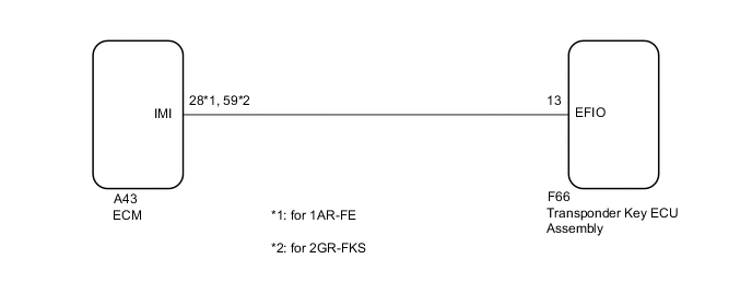
*1: for 1AR-FE
-
*2: for 2GR-FKS
WIRING DIAGRAM
CAUTION / NOTICE / HINT
Note
-
If the transponder key ECU assembly or ECM is replaced, refer to Service Bulletin.
-
After repair, confirm that no DTCs are output by performing "DTC Output Confirmation Operation".
PROCEDURE
-
CLEAR DTC
-
Clear the DTCs.
Powertrain > Engine and ECT > Clear DTCs
Powertrain > Engine > Clear DTCsResult Proceed to NEXT
NEXT 
-
-
CHECK FOR DTC
-
Perform "DTC Output Confirmation Operation" procedure.
-
Check for DTCs.
Powertrain > Engine and ECT > Trouble Codes
Powertrain > Engine > Trouble CodesOK DTC B279A*1 or B279A12*2 is not output. Result Result Proceed to B279A*1 or B279A12*2 is not output A B279A*1 or B279A12*2 is output B
-
*1: for 1AR-FE
-
*2: for 2GR-FKS
-
A 
USE SIMULATION METHOD TO CHECK Click here
B
-
-
CHECK CONNECTION OF CONNECTOR
-
Check that the connectors are properly connected to the ECM and transponder key ECU assembly.
OK Connectors are properly connected. Result Proceed to OK NG
NG
CONNECT CONNECTORS PROPERLY
OK
-
-
CHECK HARNESS AND CONNECTOR (TRANSPONDER KEY ECU ASSEMBLY - ECM)
-
Disconnect the F66 transponder key ECU assembly connector.
-
Disconnect the A43 ECM connector.
-
Measure the resistance according to the value(s) in the table below.
Standard Resistance Tester Connection Condition Specified Condition F66-13 (EFIO) - A43-28 (IMI)*1 Always Below 1 Ω F66-13 (EFIO) - A43-59 (IMI)*2 Always Below 1 Ω A43-28 (IMI) or F66-13 (EFIO) - Body ground*1 Always 10 kΩ or higher A73-59 (IMI) or F66-13 (EFIO) - Body ground*2 Always 10 kΩ or higher
-
*1: for 1AR-FE
-
*2: for 2GR-FKS
Result Proceed to OK NG -
NG
REPAIR OR REPLACE HARNESS OR CONNECTOR
OK
-
-
REPLACE TRANSPONDER KEY ECU ASSEMBLY
-
Replace the transponder key ECU assembly with a new one.
Tech Tips
Refer to Service Bulletin.
Note
Key ID code registration is necessary when replacing the transponder key ECU assembly, refer to Service Bulletin.
Result Proceed to NEXT
NEXT
-
-
CLEAR DTC
-
Clear the DTCs.
Powertrain > Engine and ECT > Clear DTCs
Powertrain > Engine > Clear DTCsResult Proceed to NEXT
NEXT
-
-
CHECK FOR DTC
-
Perform "DTC Output Confirmation Operation" procedure.
-
Check for DTCs.
Powertrain > Engine and ECT > Trouble Codes
Powertrain > Engine > Trouble CodesOK DTC B279A*1 or B279A12*2 is not output. Result Result Proceed to B279A*1 or B279A12*2 is not output A B279A*1 or B279A12*2 is output B
-
*1: for 1AR-FE
-
*2: for 2GR-FKS
-
A
END (TRANSPONDER KEY ECU ASSEMBLY WAS DEFECTIVE)
B
REPLACE ECM for 1AR-FE: Click here
REPLACE ECM for 2GR-FKS: Click here -