THEFT DETERRENT SYSTEM Unlock Warning Switch Circuit
DESCRIPTION
The unlock warning switch assembly comes on when the key is inserted into the ignition key cylinder and goes off when the key is removed.
WIRING DIAGRAM
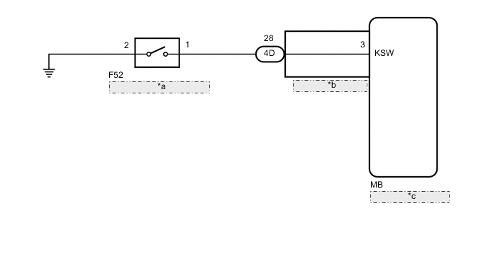
| *a | Unlock Warning Switch Assembly |
| *b | Instrument Panel Junction Block Assembly |
| *c | Main Body ECU (Multiplex Network Body ECU) |
CAUTION / NOTICE / HINT
Note
-
As the door control battery is installed between the vehicle battery and main body ECU (multiplex network body ECU), first perform the inspections in On-Vehicle Inspection to confirm that there are no malfunctions in the power source circuit for the main body ECU (multiplex network body ECU) before performing this troubleshooting procedure.*
-
*: for LHD
PROCEDURE
-
READ VALUE USING GTS (KEY UNLOCK WARNING SW)
-
Connect the GTS to the DLC3.
-
Turn the ignition switch to ON.
-
Turn the GTS on.
-
Enter the following menus: Body Electrical / Main Body / Data List.
-
Read the Data List according to the display on the GTS.
Body Electrical > Main Body > Data ListTester Display Measurement Item Range Normal Condition Diagnostic Note Key Unlock Warning SW Unlock warning switch ON or OFF ON: Key inserted into ignition key cylinder
OFF: Key removed from ignition key cylinder
-
Body Electrical > Main Body > Data ListTester Display Key Unlock Warning SW OK The GTS display changes correctly in response to the unlock warning switch assembly status. Result Proceed to OK NG
OK 
PROCEED TO NEXT SUSPECTED AREA SHOWN IN PROBLEM SYMPTOMS TABLE Click here
NG 
-
-
INSPECT UNLOCK WARNING SWITCH ASSEMBLY
-
Remove the unlock warning switch assembly.
-
Inspect the unlock warning switch assembly.
Result Proceed to OK NG
NG
REPLACE UNLOCK WARNING SWITCH ASSEMBLY Click here
OK
-
-
INSPECT INSTRUMENT PANEL JUNCTION BLOCK ASSEMBLY
-
Remove the main body ECU (multiplex network body ECU).
*a Component without harness connected
(Instrument Panel Junction Block Assembly)
- - -
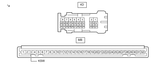
Disconnect the 4D instrument panel junction block assembly connector.
-
Measure the resistance according to the value(s) in the table below.
Standard Resistance Tester Connection Condition Specified Condition 4D-28 - MB-3 (KSW) Always Below 1 Ω Result Proceed to OK NG
NG
REPLACE INSTRUMENT PANEL JUNCTION BLOCK ASSEMBLY Click here
OK
-
-
CHECK HARNESS AND CONNECTOR (INSTRUMENT PANEL JUNCTION BLOCK ASSEMBLY - UNLOCK WARNING SWITCH ASSEMBLY - BODY GROUND)
-
Measure the resistance according to the value(s) in the table below.
Standard Resistance Tester Connection Condition Specified Condition 4D-28 - F52-1 Always Below 1 Ω 4D-28 or F52-1 - Body ground Always 10 kΩ or higher F52-2 - Body ground Always Below 1 Ω Result Proceed to OK NG
OK
REPLACE MAIN BODY ECU (MULTIPLEX NETWORK BODY ECU) Click here
NG
REPAIR OR REPLACE HARNESS OR CONNECTOR
-