AUTOMATIC TRANSAXLE ASSEMBLY(When Using the Engine Support Bridge) REMOVAL

PROCEDURE
-
PRECAUTION
Note
After turning the engine switch off, waiting time may be required before disconnecting the cable from the negative (-) battery terminal. Therefore, make sure to read the disconnecting the cable from the negative (-) battery terminal notices before proceeding with work.
-
ALIGN FRONT WHEELS FACING STRAIGHT AHEAD
-
SECURE STEERING WHEEL
-
DISCONNECT CABLE FROM NEGATIVE BATTERY TERMINAL
Note
When disconnecting the cable, some systems need to be initialized after the cable is reconnected.
-
REMOVE FRONT WHEELS
-
REMOVE WINDSHIELD WIPER MOTOR AND LINK ASSEMBLY
-
REMOVE OUTER COWL TOP PANEL SUB-ASSEMBLY (for LHD)
-
REMOVE OUTER COWL TOP PANEL SUB-ASSEMBLY (for RHD)
-
REMOVE NO. 1 ENGINE UNDER COVER
-
REMOVE NO. 2 ENGINE UNDER COVER
-
REMOVE FRONT FLOOR COVER LH
-
SEPARATE FRONT FENDER LINER LH
-
SEPARATE FRONT FENDER LINER RH
-
REMOVE FRONT FENDER APRON SEAL LH
-
REMOVE FRONT FENDER APRON SEAL RH
-
DRAIN ENGINE COOLANT
-
DRAIN AUTOMATIC TRANSAXLE FLUID
-
DRAIN TRANSFER OIL
-
REMOVE STARTER ASSEMBLY
-
SEPARATE TRANSMISSION CONTROL CABLE ASSEMBLY
-
DISCONNECT ENGINE WIRE
-
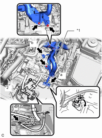
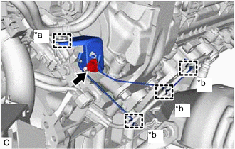
*a Transmission Wire Connector *b Park/Neutral Position Switch Assembly Connector *1 Engine Wire *2 Earth Wire Disconnect the park/neutral position switch assembly connector.
-
Disengage the claw, rotate the lever and disconnect the connector of the transmission wire connector.
-
Remove the 2 bolts and nut, disconnect the engine wire from the automatic transaxle case sub-assembly.
-
Remove the bolt to separate the earth wire.
-
Disengage the clamp to separate the engine wire.
-
-
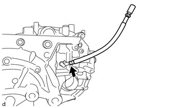
SEPARATE BREATHER PLUG HOSE
-
Disengage the 3 hose clamps to separate the breather plug hose.
-
-
DISCONNECT NO. 4 WATER BY-PASS HOSE
-
DISCONNECT NO. 3 WATER BY-PASS HOSE
-
REMOVE RADIATOR PIPE ASSEMBLY
-
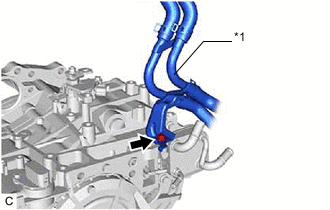
*1 Radiator Pipe Assembly Remove the bolt and radiator pipe assembly from the automatic transaxle assembly.
-
-
DISCONNECT OUTLET NO. 1 OIL COOLER HOSE
-
DISCONNECT NO. 1 TRANSMISSION OIL COOLER HOSE
-
SEPARATE BRAKE MASTER CYLINDER RESERVOIR ASSEMBLY (for LHD)
-
REMOVE THROTTLE BODY WITH MOTOR ASSEMBLY
-
DISCONNECT VENTILATION HOSE
-
DISCONNECT PURGE VALVE (PURGE VSV)
-
REMOVE NO. 2 SURGE TANK STAY
-
REMOVE INTAKE AIR SURGE TANK ASSEMBLY
-
REMOVE AIR SURGE TANK TO INTAKE MANIFOLD GASKET
-
REMOVE WIRE HARNESS CLAMP BRACKET
-
Disconnect the air fuel ratio sensor (for Bank 1) connector.
-
*a Hose Clamp *b Wire Harness Clamp Disengage the hose clamp and 3 wire harness clamps.
-
Remove the bolt and wire harness clamp bracket from the cylinder head RH.
-
-
REMOVE FRONT NO. 3 EXHAUST PIPE SUB-ASSEMBLY
-
REMOVE NO. 1 EXHAUST PIPE SUPPORT BRACKET (for Lower Side)
-
REMOVE FRONT EXHAUST PIPE ASSEMBLY
-
REMOVE MANIFOLD STAY
-
REMOVE EXHAUST MANIFOLD (TWC: Front Catalyst)
-
REMOVE EXHAUST MANIFOLD TO HEAD GASKET (for Bank 1)
-
REMOVE PROPELLER WITH CENTER BEARING SHAFT ASSEMBLY
-
SEPARATE FRONT STABILIZER LINK ASSEMBLY LH
-
SEPARATE FRONT STABILIZER LINK ASSEMBLY RH
Tech Tips
Use the same procedure as for the LH side.
-
REMOVE FRONT AXLE SHAFT NUT
-
SEPARATE FRONT SPEED SENSOR
-
SEPARATE STEERING INTERMEDIATE SHAFT ASSEMBLY
-
SEPARATE TIE ROD ASSEMBLY LH
-
SEPARATE TIE ROD ASSEMBLY RH
Tech Tips
Use the same procedure as for the LH side.
-
SEPARATE STEERING LINK ASSEMBLY
-
SEPARATE FRONT LOWER NO. 1 SUSPENSION ARM SUB-ASSEMBLY LH
-
SEPARATE FRONT LOWER NO. 1 SUSPENSION ARM SUB-ASSEMBLY RH
Tech Tips
Use the same procedure as for the LH side.
-
SEPARATE FRONT DRIVE SHAFT ASSEMBLY
-
REMOVE FRONT DRIVE SHAFT ASSEMBLY LH
-
REMOVE FRONT DRIVE SHAFT HOLE SNAP RING (for LH Side)
-
SEPARATE FRONT NO. 1 STABILIZER BRACKET LH
-
SEPARATE FRONT NO. 1 STABILIZER BRACKET RH
Tech Tips
Use the same procedure as for the LH side.
-
REMOVE FRONT STABILIZER BAR WITH FRONT STABILIZER LINK ASSEMBLY
-
Remove the front stabilizer bar with front stabilizer link assembly from the front frame assembly.
Note
Use wire or an equivalent tool to secure the front stabilizer bar with front stabilizer link assembly.
-
-
REMOVE STEERING LINK ASSEMBLY
-
Remove the steering link assembly from the vehicle body.
-
-
SEPARATE TRANSMISSION OIL THERMOSTAT
-
SEPARATE FRONT ENGINE MOUNTING INSULATOR ASSEMBLY
-
SEPARATE ENGINE MOUNTING INSULATOR LH
-
SEPARATE ENGINE MOUNTING INSULATOR RH
-
SEPARATE REAR ENGINE MOUNTING INSULATOR ASSEMBLY
-
INSTALL ENGINE HANGER
-
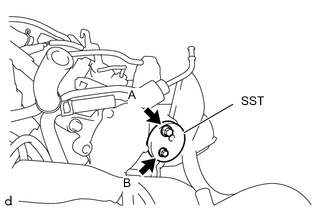
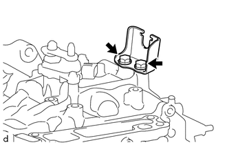
Install SST (engine hanger attachment) to the cylinder head RH with the 2 bolts.
- SST
- 09940-30010 ( 91671-10825 )
- Torque:
- Bolt (A)
- 33 N*m { 337 kgf*cm, 24 ft.*lbf }
- Bolt (B)
- 10 N*m { 102 kgf*cm, 7 ft.*lbf }
Item Part No. Bolt (A) 91671-10825 Bolt (B) 91551-80620 Note
Do not use any bolts other than the specified bolts.
-
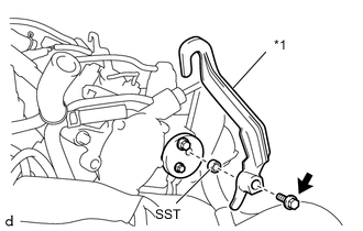
*1 No. 1 Engine Hanger Install SST (collar) and No. 1 engine hanger to SST (engine hanger attachment) with the bolt.
- SST
- 09940-30010 ( 09941-03010 )
- Torque:
- 43 N*m { 438 kgf*cm, 32 ft.*lbf }
Item Part No. No. 1 Engine Hanger 12281-36020 Bolt 91552-81050 Note
Do not use any bolts other than the specified bolt.
-
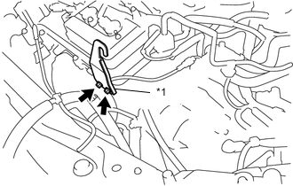
*1 No. 2 Engine Hanger Install the No. 2 engine hanger to the cylinder head LH with the 2 bolts.
- Torque:
- 33 N*m { 337 kgf*cm, 24 ft.*lbf }
Item Part No. No. 2 Engine Hanger 12282-31100 Bolt 91671-10825 Note
Do not use any bolts other than the specified bolts.
-
-
INSTALL ENGINE SUPPORT BRIDGE
-
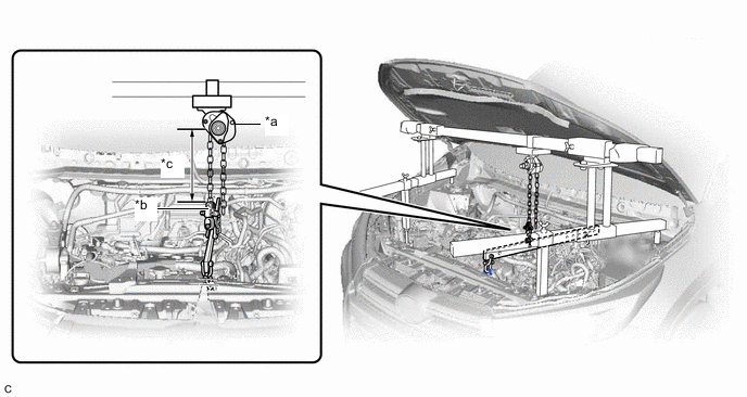
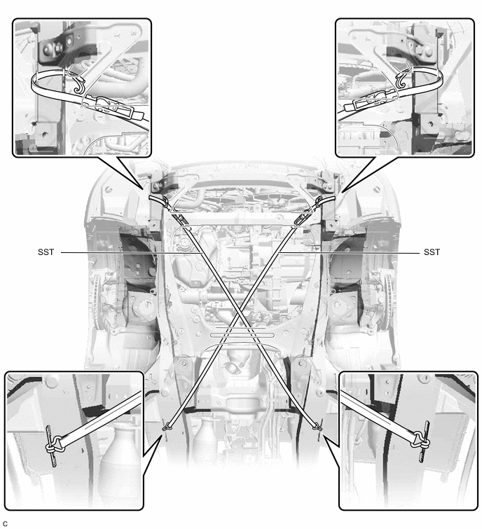
Install SST to the vehicle body as shown in the illustration.
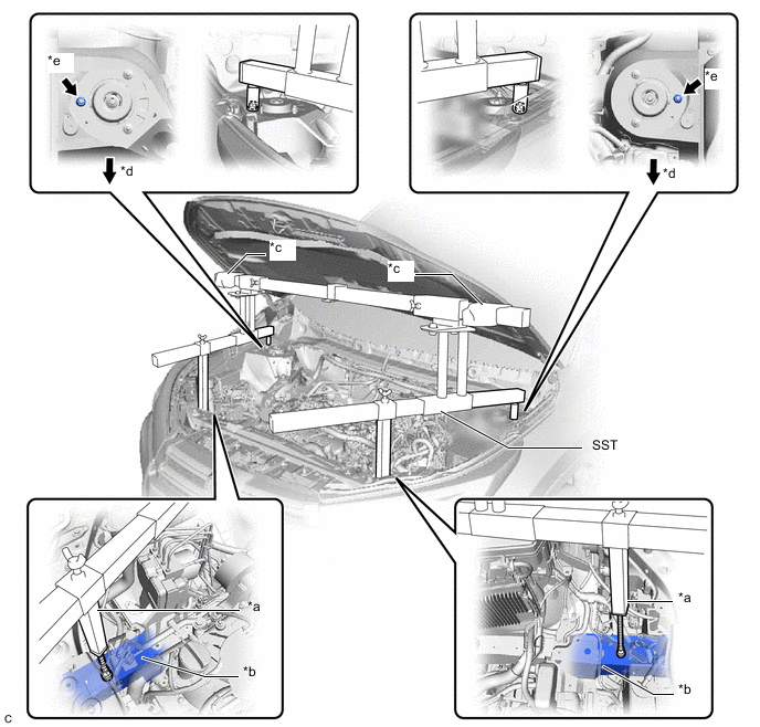
*a Support Shaft *b Front Side Member *c Cloth *d Front Side *e Front Suspension Nut - - - SST
- 09940-10020
Note
-
Prevent SST from contacting the vehicle body exterior and windshield glass.
-
To prevent damage to the engine hood, place pieces of cloth between the engine hood and SST.
-
Lightly shake SST by hand to make sure it is securely installed before performing work.
-
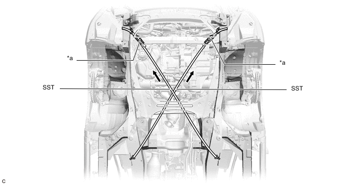
*a Support Shaft *b Sub Beam *c Front Side Member *d Threaded Portion Turn the threaded portion of each support shaft to adjust its height until the sub beams are parallel to the ground.
-
Install the chain block to the sling bracket.
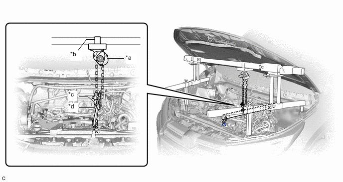
*a Chain Block *b Sling Bracket *c Fuse Shackle *d Shackle (A) -
Install the division bar to the chain block with the fuse shackle and shackle (A).
-
Connect the division bar to the No. 1 engine hanger with the shackle (A).
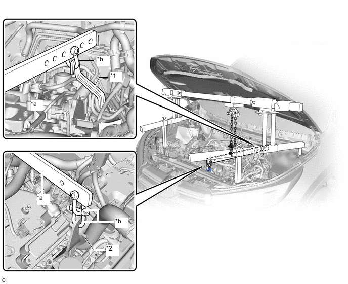
*1 No. 1 Engine Hanger *2 No. 2 Engine Hanger *a Division Bar *b Shackle (A) -
Connect the division bar to the No. 2 engine hanger with the 2 shackles (A).
-
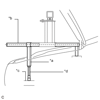
Make sure the distance between the chain block assembly and suspension ring is 120 mm (4.72 in.) or more.
*a Chain Block Assembly *b Suspension Ring *c 120 mm or more - - -
Adjust the position of the chain block assembly so that the chain is perpendicular to the main beam and sub beams as shown in the illustration.
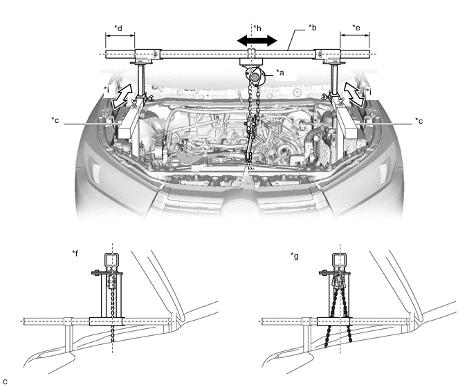
*a Chain Block Assembly *b Main Beam *c Sub Beam *d Dimension (A) *e Dimension (B) *f Correct *g Incorrect *h Right to Left Adjustment *i Front to Rear Adjustment - - -
Tighten the 6 wing bolts and 2 bolts.
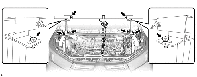
- Torque:
- 30 N*m { 306 kgf*cm, 22 ft.*lbf }
CAUTION:
-
Do not perform any procedures before tightening the bolts to the specified torque.
-
Performing procedures without tightening the bolts to the specified torque, may cause the engine support bridge to fall.
-
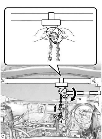
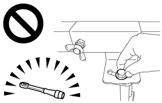
*a Turn Tighten the chain block assembly until it cannot be moved any further by hand.
-
-
REMOVE FLYWHEEL HOUSING UNDER COVER
-
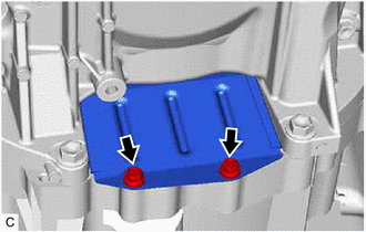
Remove the 2 bolts and flywheel housing under cover from the automatic transaxle case sub-assembly.
-
-
REMOVE DRIVE PLATE AND TORQUE CONVERTER ASSEMBLY SETTING BOLT
-
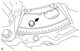
Turn the crankshaft to gain access to the 6 drive plate and torque converter assembly setting bolts and remove each drive plate and torque converter assembly setting bolt while holding the crankshaft pulley bolt with a wrench.
Tech Tips
There will be one black colored drive plate and torque converter assembly setting bolt.
-
-
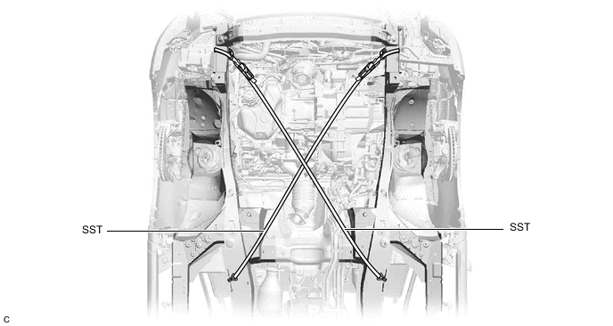
INSTALL BELT
-
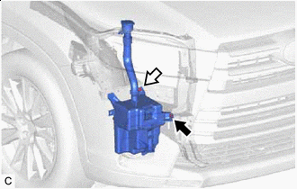

Bolt 
Nut Remove the bolt and nut and disconnect the windshield washer jar assembly from the vehicle body.
-
Install SST to the vehicle body as shown in the illustration.
- SST
- 09727-00110
-
Using the ratchet buckle, tighten the 2 belts until there is no slack.
*a Ratchet Buckle - -
-
-
REMOVE FRONT FRAME ASSEMBLY
-
REMOVE TRANSFER STIFFENER PLATE RH
-
Remove the 4 bolts and transfer stiffener plate RH.
-
-
REMOVE ENGINE MOUNTING INSULATOR RH
-
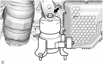
Remove the nut and engine mounting insulator RH from the engine mounting bracket RH.
-
-
REMOVE FRONT DRIVE SHAFT ASSEMBLY RH
-
INSTALL ENGINE SUPPORT BAR
-
Install SST (support bar) to the engine mounting bracket RH with the stud bolt and nut as shown in the illustration.
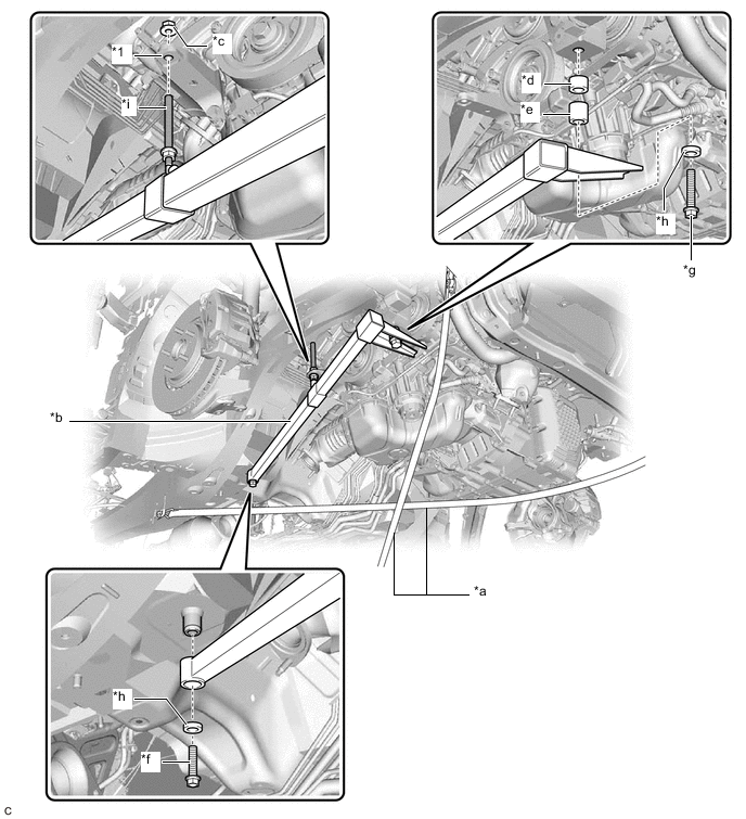
Text in Illustration *1 Engine Mounting Bracket RH - - *a SST (Belt) *b SST (Support Bar) *c SST (Nut) *d SST (Spacer 20) *e SST (Spacer 30) *f SST (Bolt 40) *g SST (Bolt 90) *h SST (Washer) *i Stud Bolt - - - SST
- 09940-20011 ( 09941-02010, 09941-02020, 09941-02030, 09941-02040, 09941-02050, 09941-02060, 09941-02070 )
CAUTION:
To prevent the engine with automatic transaxle assembly from falling while servicing, do not remove SST (belt).
Tech Tips
Tighten the nut by hand.
-
Install SST (support bar) to the vehicle body with the 2 bolts.
- Torque:
- 30 N*m { 306 kgf*cm, 22 ft.*lbf }
-
-
REMOVE FRONT ENGINE MOUNTING INSULATOR ASSEMBLY
-
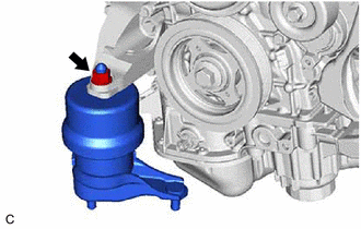
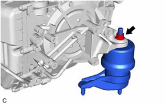
Remove the bolt and front engine mounting insulator assembly from the front engine mounting bracket.
-
-
REMOVE ENGINE MOUNTING INSULATOR LH
-
Remove the nut and engine mounting insulator LH from the automatic transaxle assembly.
-
-
SUPPORT ENGINE ASSEMBLY
-
Set an engine lifter.
CAUTION:
To prevent the engine assembly with automatic transaxle assembly from falling while servicing, do not remove SST.
Note
Make sure that there is clearance between the engine oil pan assembly and engine lifter.
-
-
REMOVE BELT
-
Remove SST from the vehicle body.
-
-
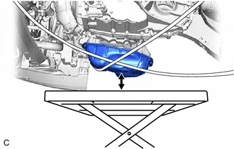
REMOVE AUTOMATIC TRANSAXLE ASSEMBLY
-
Support the automatic transaxle assembly with a transmission jack.
Note
Secure the automatic transaxle assembly to the transmission jack using a suitable adapter, such as a rope or attachments.
-
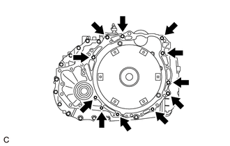
Remove the 11 bolts and automatic transaxle assembly.
Note
To prevent damage to the knock pins, do not pry between the automatic transaxle assembly and engine assembly.
-
-
REMOVE TRANSFER ASSEMBLY
-
DISCONNECT INLET NO. 2 OIL COOLER HOSE
-
DISCONNECT OUTLET NO. 3 OIL COOLER HOSE
-
REMOVE NO. 1 OIL COOLER TUBE SUB-ASSEMBLY WITHOUT HOSE
-
REMOVE TRANSMISSION OIL COOLER
-
REMOVE FRONT ENGINE MOUNTING BRACKET
-
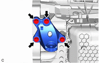
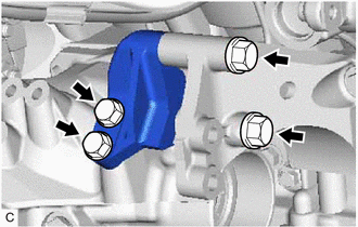
Remove the 4 bolts and front engine mounting bracket from the automatic transaxle assembly.
-
-
REMOVE ENGINE MOUNTING BRACKET LH
-
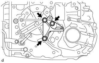
Remove the 3 bolts and engine mounting bracket LH from the automatic transaxle case sub-assembly.
-
-
REMOVE NO. 1 TRANSMISSION CONTROL CABLE BRACKET
-
Remove the 2 bolts and No. 1 transmission control cable bracket from the automatic transaxle case sub-assembly.
-
-
REMOVE WIRE HARNESS CLAMP BRACKET
-
Remove the bolt and wire harness clamp bracket from the automatic transaxle case sub-assembly.
-
-
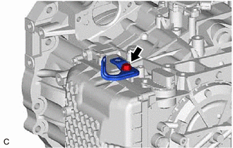
REMOVE TRANSMISSION CASE PLUG ASSEMBLY
-
Remove the transmission case plug assembly from the automatic transaxle assembly.
-
-
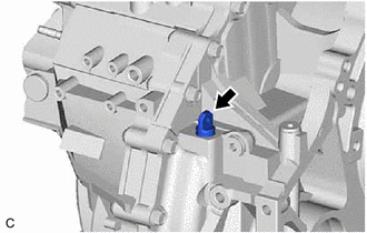
REMOVE BREATHER PLUG HOSE
-
Using a screwdriver, remove the breather plug hose from the No. 1 breather plug (ATM).
Note
Be careful not to damage the No. 1 breather plug (ATM).
-

*1 Breather Plug Sub-assembly *2 Breather Plug Hose Remove the breather plug sub-assembly from the breather plug hose.
Note
Be careful not to damage the breather plug sub-assembly.
-
-
REMOVE TORQUE CONVERTER ASSEMBLY
-
Remove the torque converter assembly from the automatic transaxle assembly.
-
-
INSPECT TORQUE CONVERTER ASSEMBLY
-
INSPECT DRIVE PLATE AND RING GEAR SUB-ASSEMBLY