TRANSMISSION WIRE(When Not Using the Engine Support Bridge) INSTALLATION
PROCEDURE
-
INSTALL TRANSMISSION WIRE
-
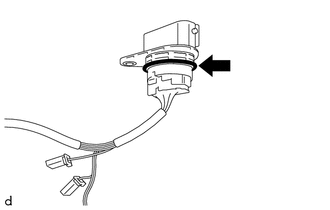
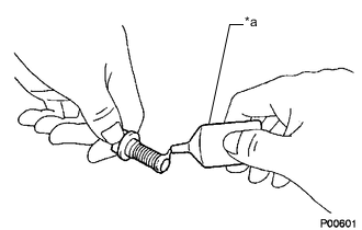
Coat the O-ring of the transmission wire with Toyota Genuine ATF WS.
-
Install the transmission wire to the automatic transaxle case sub-assembly with the bolt.
- Torque:
- 5.4 N*m { 55 kgf*cm, 48 in.*lbf }
-
Connect the transmission revolution sensor (NT) connector and transmission revolution sensor (NC) connector.
-
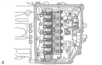
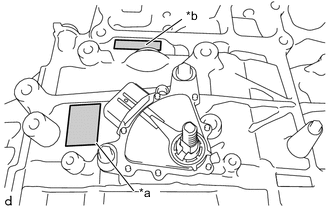
Install the temperature sensor to the transmission valve body assembly with the bolt and temperature sensor clamp.
- Torque:
- 10.8 N*m { 110 kgf*cm, 8 ft.*lbf }
Note
To prevent it from being pinched between the transmission valve body assembly and the transmission case side cover, pass the transmission revolution sensor (NC) wire under the transmission wire (temperature sensor wire) as shown in the illustration.

*a Transmission Wire (Temperature Sensor Wire) *b Transmission Revolution Sensor (NC) Wire -
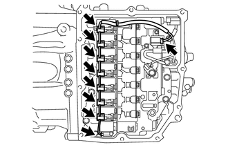
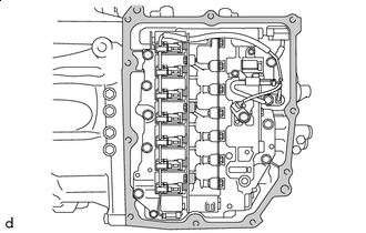
Connect the 9 solenoid valve connectors.
Note

Do not let transmission wire protrude into this area.
-
To prevent it from being pinched between the transmission valve body assembly and the transmission case side cover, do not let the transmission wire ride up over the area shown in the illustration.
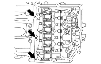
-
To prevent it from being pinched between the transmission case side cover and the automatic transaxle case sub-assembly, do not let the transmission wire protrude toward the transmission case side cover installation surface.
-
-
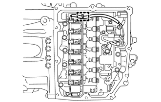
Engage the clamp to connect the transmission wire to the solenoid lock plate.
-
-
INSTALL TRANSMISSION CASE SIDE COVER (for TMC Made)
Tech Tips
TMC (TOYOTA) Made and AW (AISIN AW) Made components can be identified by the differing locations where the serial number is stamped.
*a TMC Made *b AW Made
-
Area to be cleaned Clean the transmission case side cover installation surface of the automatic transaxle case sub-assembly.
Note
Completely remove any oil or grease from the contact surfaces of the automatic transaxle case sub-assembly.
-
Clean the 3 bolt holes shown in the illustration.
-
*a Adhesive Apply adhesive to 2 or 3 threads on the end of the bolt (A) and 2 bolts (D).
Adhesive Toyota Genuine Adhesive 1324, Three Bond 1324 or equivalent Note
Make sure to install the bolts immediately after applying adhesive to prevent foreign matter from attaching to them.
Tech Tips
The bolt (A) and 2 bolts (D) are in the locations shown in the following step.
-

Temporarily install a new transmission case side cover to the automatic transaxle case sub-assembly with the 2 bolts ((A) and (B)).
Note
-
Bolt (A) is an adhesive-coated bolt.
-
To avoid damaging the gasket, prevent it from contacting the surrounding area during installation procedures.
-
-
Temporarily install the 6 bolts (C) and 2 bolts (D).
Note
Bolt (D) is an adhesive-coated bolt.
-
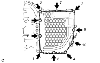
Fully tighten the 10 bolts in the order shown in the illustration.
- Torque:
- Bolt (A) and Bolt (D)
- 6.5 N*m { 66 kgf*cm, 58 in.*lbf }
- Bolt (B) and Bolt (C)
- 7.0 N*m { 71 kgf*cm, 62 in.*lbf }
-
-
INSTALL TRANSMISSION CASE SIDE COVER (for AISIN AW Made)
Tech Tips
TMC (TOYOTA) Made and AW (AISIN AW) Made components can be identified by the differing locations where the serial number is stamped.
*a TMC Made *b AW Made
-
Area to be cleaned Clean the transmission case side cover installation surface of the automatic transaxle case sub-assembly.
Note
Completely remove any oil or grease from the contact surfaces of the automatic transaxle case sub-assembly.
-
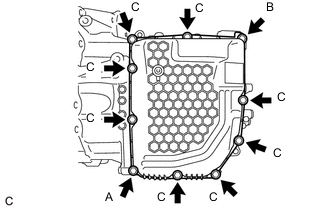
Temporarily install a new transmission case side cover to the automatic transaxle case sub-assembly with the 2 bolts (A and B).
Note
To avoid damaging the gasket, prevent it from contacting the surrounding area during installation procedures.
-
Temporarily install the 8 bolts (C).
-

Fully tighten the 10 bolts in the order shown in the illustration.
- Torque:
- 7.0 N*m { 71 kgf*cm, 62 in.*lbf }
-
-
INSTALL OIL COOLER UNION SUB-ASSEMBLY
-
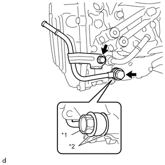
*1 Oil Cooler Union Bolt *2 Gasket Pass the oil cooler union sub-assembly through 2 new gaskets and temporarily install it to the automatic transaxle case sub-assembly.
-
Temporarily install the oil cooler union sub-assembly bracket portion to the automatic transaxle case sub-assembly with the bolt.
-
Fully tighten the oil cooler union bolt.
- Torque:
- 22.6 N*m { 230 kgf*cm, 17 ft.*lbf }
-
Fully tighten the bolt.
- Torque:
- 12 N*m { 122 kgf*cm, 9 ft.*lbf }
-
-
INSTALL TORQUE CONVERTER ASSEMBLY
-
INSTALL AUTOMATIC TRANSAXLE ASSEMBLY