AUTOMATIC TRANSAXLE ASSEMBLY INSTALLATION
PROCEDURE
-
INSTALL TORQUE CONVERTER ASSEMBLY
-
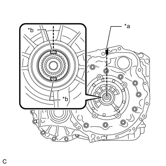
*a Matchmark *b Key Turn the front oil pump drive gear so that the key is at the top and place a matchmark on the transaxle housing to indicate the position of the key.
-
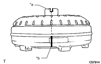
*a Groove *b Matchmark Place a matchmark on the torque converter assembly so that the position of its groove is clearly indicated.
-
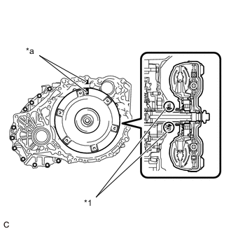
*1 Front Oil Pump Oil Seal *a Matchmark Align the matchmark on the transaxle housing with the one on the torque converter assembly and engage the splines of the input shaft with the turbine runner splines.
Note
-
Install the torque converter assembly to the input shaft while keeping it horizontal.
-
Do not damage the front oil pump oil seal.
-
-
*1 Front Oil Pump Oil Seal *a Matchmark Rotate the torque converter assembly approximately 180° and engage the splines of the stator shaft with the stator assembly.
Note
-
Install the torque converter assembly to the input shaft while keeping it horizontal.
-
Do not damage the front oil pump oil seal.
-
-
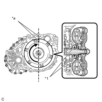
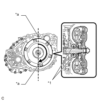
*1 Front Oil Pump Oil Seal *a Matchmark Rotate the torque converter assembly approximately 180° again, align the matchmark on the torque converter assembly with the one on the transaxle housing and insert the groove of the torque converter assembly into the key of the front oil pump drive gear.
Note
-
Do not push the torque converter assembly excessively when rotating it.
-
Install the torque converter assembly to the input shaft while keeping it horizontal.
-
Do not damage the front oil pump oil seal.
-
-
Clean the drive plate and torque converter assembly setting bolt holes.
-
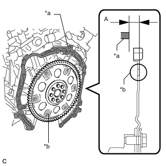
*a Engine Surface *b Drive Plate Surface Using a vernier caliper and straightedge, measure the dimension (A) between the automatic transaxle assembly contact surface of the engine assembly*a and the torque converter assembly contact surfaces of the drive plate*b.
-
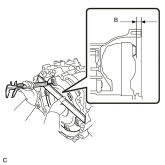
Using a vernier caliper and straightedge, measure the dimension (B) shown in the illustration and check that the dimension (B) is more than the dimension (A), which was measured in the previous step.
Standard A + 1 mm (0.0394 in.) or more Note
-
Make sure to deduct the thickness of the straightedge.
-
If the automatic transaxle assembly is installed to the engine assembly with the torque converter assembly not sufficiently inserted, the torque converter assembly may be damaged.
-
Do not include the thickness of the set block.
-
-
-
INSTALL SPEEDOMETER DRIVEN HOLE (ATM) COVER SUB-ASSEMBLY
-
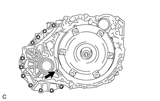
Apply ATF to a new O-ring and install it to the speedometer driven hole (ATM) cover sub-assembly.
-
Install the speedometer driven hole (ATM) cover sub-assembly to the automatic transaxle assembly with the bolt.
- Torque:
- 5.5 N*m { 56 kgf*cm, 49 in.*lbf }
-
-
INSTALL NO. 1 TRANSMISSION CONTROL CABLE BRACKET
-
Install the No. 1 transmission control cable bracket to the automatic transaxle assembly with the 2 bolts.
- Torque:
- 12 N*m { 122 kgf*cm, 9 ft.*lbf }
-
-
INSTALL WIRE HARNESS CLAMP BRACKET
-
Install the 4 wire harness clamp brackets to the automatic transaxle assembly with the 4 bolts.
- Torque:
- 8.0 N*m { 82 kgf*cm, 71 in.*lbf }
-
-
INSTALL FRONT ENGINE MOUNTING BRACKET
-
Install the front engine mounting bracket to the automatic transaxle assembly with the 3 bolts.
- Torque:
- 64 N*m { 652 kgf*cm, 47 ft.*lbf }
-
-
INSTALL TRANSFER ASSEMBLY
-
INSTALL AUTOMATIC TRANSAXLE ASSEMBLY
-
Clean and degrease the bolt and bolt hole in the automatic transaxle assembly.
-
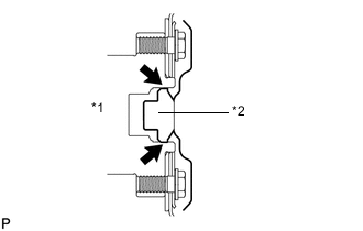
*1 Crankshaft *2 Torque Converter Assembly Centerpiece Apply clutch spline grease to the surface of the crankshaft that contacts the torque converter assembly centerpiece.
Clutch Spline Grease Toyota Genuine Clutch Spline Grease or equivalent Maximum Grease Amount Approximately 1 g (0.0353 oz.) -
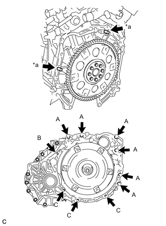
*a Knock Pin While keeping the engine assembly and automatic transaxle assembly horizontal, align the knock pins with the holes in the automatic transaxle assembly and temporarily install the 10 bolts shown in the illustration.
- Torque:
- Bolt (A)
- 64 N*m { 653 kgf*cm, 47 ft.*lbf }
- Bolt (B)
- 64 N*m { 653 kgf*cm, 47 ft.*lbf }
- Bolt (C)
- 43 N*m { 438 kgf*cm, 32 ft.*lbf }
Note
-
Confirm that the 2 knock pins are installed to the automatic transaxle assembly contact surface of the engine cylinder block before installing the automatic transaxle assembly.
-
Do not forcibly pry on the automatic transaxle assembly.
-
Check that the torque converter assembly rotates.
Tech Tips
Bolt length:
-
Bolt (A): 55 mm (2.17 in.)
-
Bolt (B): 50 mm (1.97 in.)
-
Bolt (C): 33 mm (1.30 in.)
-
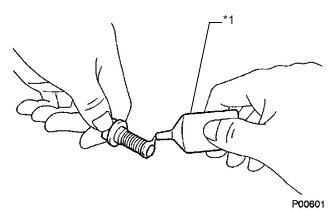
*1 Adhesive 1344 Apply a few drops of adhesive to 2 or 3 threads at the tip of the bolt.
Adhesive Toyota Genuine Adhesive 1344, Three Bond 1344 or equivalent -
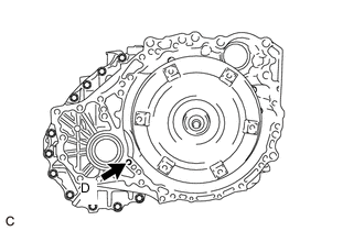
Install the bolt.
- Torque:
- Bolt (D)
- 46 N*m { 469 kgf*cm, 34 ft.*lbf }
Tech Tips
Bolt length:
-
Bolt (D): 41 mm (1.61 in.)
-
-
INSTALL TRANSFER STIFFENER PLATE RH
-
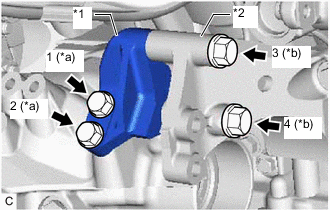
*1 Transfer Stiffener Plate RH *2 Rear Engine Mounting Bracket *a Bolt (A) *b Bolt (B) Temporarily install the transfer stiffener plate RH to the transfer assembly and the rear engine mounting bracket with the 4 bolts.
-
Install the 4 bolts in the order shown in the illustration.
- Torque:
- Bolt (A)
- 34 N*m { 347 kgf*cm, 25 ft.*lbf }
- Bolt (B)
- 78 N*m { 795 kgf*cm, 58 ft.*lbf }
-
-
INSTALL RADIATOR PIPE CLAMP
-
Install the clamp to the radiator pipe clamp.
-
Install the radiator pipe clamp with the clamp to the engine assembly with the bolt.
- Torque:
- 5.5 N*m { 56 kgf*cm, 49 in.*lbf }
-
Engage the breather plug to the clamp.
-
Engage the air fuel ratio sensor wire harness.
-
-
CONNECT WIRE HARNESS
-
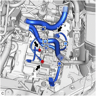
*a Park/Neutral Position Switch Connector Engage the 5 clamps to the automatic transaxle assembly.
-
Connect the wire harness to the automatic transaxle assembly with the 2 bolts.
- Torque:
- Bolt (A)
- 19 N*m { 194 kgf*cm, 14 ft.*lbf }
- Bolt (B)
- 23 N*m { 235 kgf*cm, 17 ft.*lbf }
-
Connect the park/neutral position switch connector.
-
-
INSTALL TCM
-
INSTALL MANIFOLD STAY
-
INSTALL FRONT FRAME ASSEMBLY
-
INSTALL STEERING LINK ASSEMBLY
-
INSTALL FRONT STABILIZER BAR
-
INSTALL FRONT NO. 1 STABILIZER BRACKET LH
-
INSTALL FRONT NO. 1 STABILIZER BRACKET RH
Tech Tips
Perform the same procedure as for the LH side.
-
INSTALL ENGINE ASSEMBLY WITH TRANSAXLE
-
INSTALL DRIVE PLATE AND TORQUE CONVERTER ASSEMBLY SETTING BOLT
-
*1 Adhesive 1324 Apply a few drops of adhesive to 2 or 3 threads at the tip of each of the 6 drive plate and torque converter assembly setting bolts.
Adhesive Toyota Genuine Adhesive 1324, Three Bond 1324 or equivalent. -
Turn the crankshaft to gain access to the installation locations of the 6 drive plate and torque converter assembly setting bolts and install each drive plate and torque converter setting bolt while holding the crankshaft pulley bolt with a wrench.
- Torque:
- 41 N*m { 418 kgf*cm, 30 ft.*lbf }
Note
First install the black colored bolt, and then the remaining 5 silver colored bolts.
-
-
INSTALL FLYWHEEL HOUSING UNDER COVER
-
CHECK AUTOMATIC TRANSAXLE SYSTEM
Note
If automatic transaxle parts have been replaced, refer to Parts Replacement Compensation Table to determine if any additional operations are necessary.