AUTOMATIC TRANSAXLE SYSTEM, Diagnostic DTC:P0500

| DTC Code | DTC Name |
|---|---|
| P0500 | Vehicle Speed Sensor "A" |
DESCRIPTION
The speed sensors detect the wheel speed and send the appropriate signals to the skid control ECU. The skid control ECU converts these wheel speed signals into a 4-pulse signal and outputs it to the TCM via the combination meter. The TCM determines the vehicle speed based on the frequency of these pulse signals.
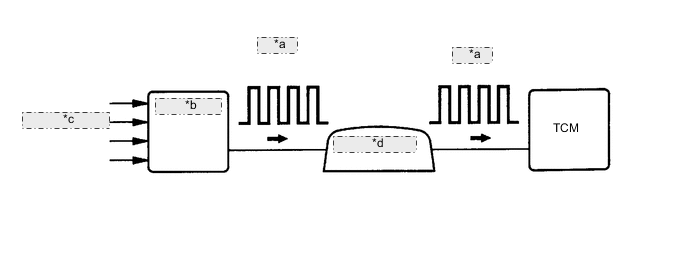
| *a | 4-Pulse |
| *b | Skid Control ECU |
| *c | from Speed Sensor |
| *d | Combination Meter |
| DTC No. | Detection Item | DTC Detection Condition | Trouble Area | MIL | Memory |
|---|---|---|---|---|---|
| P0500 | Vehicle Speed Sensor "A" | When the ECT sensor is normal and the counter gear speed is 300 rpm or more, the vehicle speed signal is not input for 2 seconds or more. |
|
Comes on | DTC stored |
MONITOR DESCRIPTION
The TCM assumes that the vehicle is being driven when the transmission counter gear indicates more than 300 rpm and over 30 seconds have passed since the park/neutral position switch assembly was turned off. If there is no vehicle speed signal with these conditions satisfied, the TCM concludes that there is a vehicle speed signal malfunction. The TCM will illuminate the MIL and store this DTC.
WIRING DIAGRAM
When a DTC P0500 is output, a ground short in the wiring of terminal SPD or an internal ground short in the relevant ECU is suspected.
PROCEDURE
-
READ VALUE USING GTS (VEHICLE SPEED)
-
Drive the vehicle and check whether the operation of the speedometer in the combination meter assembly is normal.
Tech Tips
-
The vehicle speed sensor is operating normally if the speedometer reading is normal.
-
If the speedometer does not operate, check it by following the procedure described for a speedometer malfunction.
-
-
Connect the GTS to the DLC3.
-
Turn the ignition switch to ON.
-
Turn the GTS on.
-
Enter the following menus: Powertrain / ECT / Data List / Vehicle Speed.
Powertrain > ECT > Data ListTester Display Vehicle Speed -
Drive the vehicle.
-
Read the value displayed on the GTS.
OK Vehicle speeds displayed on tester and speedometer display are equal. Result Proceed to OK NG
OK 
SYMPTOM SIMULATION AND DTC CHECK Click here
NG 
-
-
CHECK COMBINATION METER ASSEMBLY (SPD SIGNAL WAVEFORM)
-
Inspect the combination meter assembly using an oscilloscope.
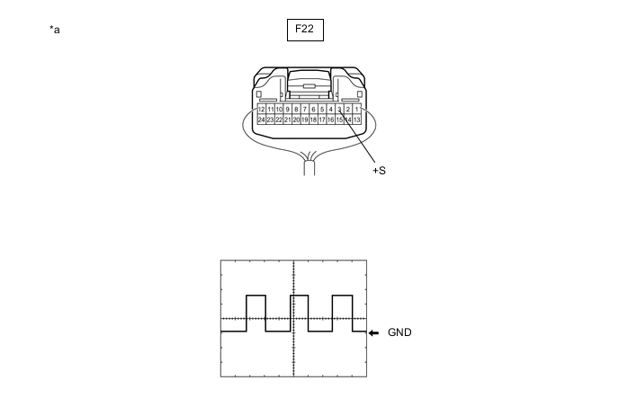
*a Component with harness connected
(Combination Meter Assembly)
- -
-
Move the shift lever to N.
-
Jack up the vehicle.
-
Turn the ignition switch to ON.
-
Measure the voltage between the terminal of the combination meter assembly and the body ground while the wheel is turned slowly.
Standard Voltage Tester Connection Condition Specified Condition F22-3 (+S) - Body ground Ignition switch ON Voltage generated intermittently Tech Tips
The output voltage should fluctuate up and down, similarly to the diagram, when the wheel is turned slowly.
Result Proceed to OK NG -
NG
GO TO METER / GAUGE SYSTEM (SPEED SIGNAL CIRCUIT) Click here
OK
-
-
CHECK HARNESS AND CONNECTOR (COMBINATION METER ASSEMBLY - TCM)
-
Disconnect the combination meter assembly connector.
-
Disconnect the TCM connector.
-
Measure the resistance according to the value(s) in the table below.
Standard Resistance (Check for Open) Tester Connection Condition Specified Condition F22-3 (+S) - C3-3 (SPD) Always Below 1 Ω Result Proceed to OK NG
OK
REPLACE TCM Click here
NG
REPAIR OR REPLACE HARNESS OR CONNECTOR (COMBINATION METER ASSEMBLY - TCM)
-